© exida.com GmbH berthold 0408-10 r003 v1r3.doc, Apr. 12, 2007
Rainer Faller Page 9 of 18
3.2 Measuring principle
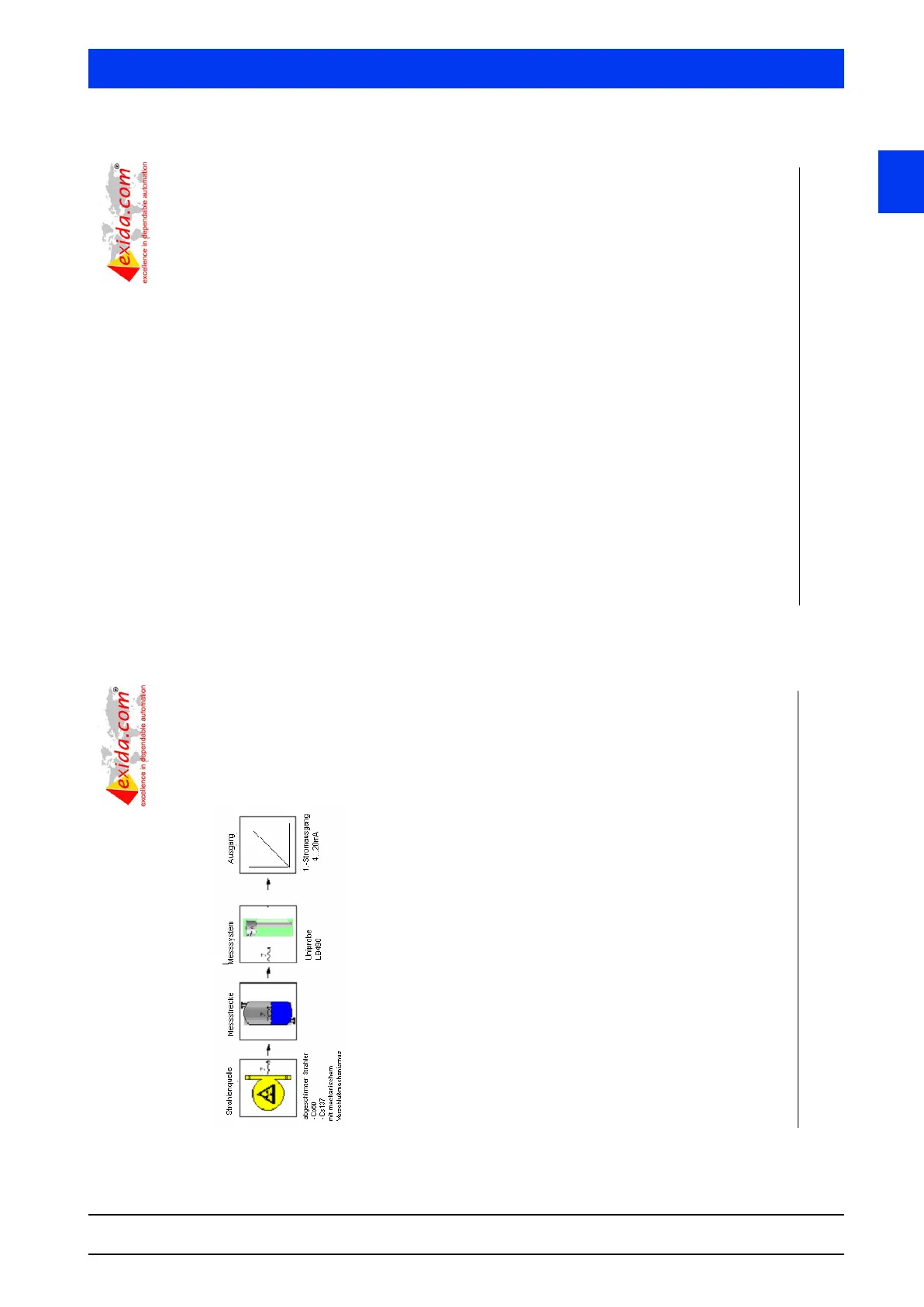
Figure 2 gives an overview of the measuring principle of the Level Transmitter LB490 Uni-Probe.
Figure 2: Measuring principle of the Level Transmitter LB490 Uni-Probe
Explanation of terms:
Strahlenquelle: Capsulated and shielded Gamma radiation source mounted outside the vessel
at the level to be monitored
Messsystem: Radiation detector mounted opposite to the source
Ausgang: 4..20mA NAMUR NE43 compliant output
The Level Switch system is based on the physical law of the attenuation of Gamma radiation as
it passes through medium. Product in between the source and the corresponding detector
decreases the detected radiation by a related extent. This effect corresponds to the relative
product's presence and therewith it signalizes the level of the product in the container (vessel,
pipe, etc.).
As it is a contact-less measurement with external mounting without modification of the existing
vessel, the measurement is independent of:
x High temperature with water-cooling
x High pressure or vacuum
x Volatile & biohazard material
x Corrosive material
x Agitators, baffles, coils etc.
x Build up on vessel walls
x Physical and chemical properties of the product and the process
Berthold Technologies main detector properties are designed according to the patented method
of automatic drift stabilization for radiometric applications, this method uses the energy loss of
natural cosmic radiation for readjustment of the amplification for measurement result
corrections. (See also Patent scripture DE 41 14030 C1)
© exida.com GmbH berthold 0408-10 r003 v1r3.doc, Apr. 12, 2007
Rainer Faller Page 10 of 18
4 Failure Modes, Effects, and Diagnostics Analysis
The Failure Modes, Effects, and Diagnostic Analysis was done together with Berthold
Technology and is documented in [R1] to [R3]. When the effect of a certain failure mode could
not be analyzed theoretically, the failure modes were introduced on component level and the
effects of these failure modes were examined on system level (see [D7] – Fault insertion tests).
This resulted in failures that can be classified according to the following failure categories.
4.1 Description of the failure categories
In order to judge the failure behavior of the Level Transmitter LB490 Uni-Probe, the following
definitions for the failure of the product were considered.
Fail-Safe State The fail-safe state is defined as the current contact reaching the
NAMUR NE43 Alarm ranges, i.e., I < 3,6mA or I > 21mA.
Fail Safe A safe failure (S) is defined as a failure that causes the transmitter
to go to the defined fail-safe state without a demand from the
process. Safe failures are divided into safe detected (SD) and safe
undetected (SU) failures.
Fail Dangerous A dangerous failure (D) is defined as a failure that does not
correctly respond to a demand from the process outside a band of
more than 5% full span at ambient temperature.
Fail Dangerous Undetected Failure that is dangerous and that is not being diagnosed by
internal diagnostics.
Fail Dangerous Detected Failure that is dangerous but is detected by internal diagnostics or
a connected logic solver (These failures may be converted to the
selected fail-safe state).
Annunciation Failure, e.g. in a diagnostic circuit, that does not directly impact
safety but impacts the ability to detect a future fault. Annunciation
failures are divided into annunciation detected (AD) and
annunciation undetected (AU) failures. For the calculation of the
Safe Failure Fraction (SFF), they are treated like dangerous
failures. This is a worst-case interpretation.
No Effect failures Failure of a component that is part of the safety function but has
no effect on the safety function within a band of not more than 5%
full span. For the calculation of the Safe Failure Fraction (SFF), it
is treated like a safe undetected failure.
The failure categories listed above expand on the categories listed in IEC 61508 which are only
safe and dangerous, both detected and undetected. The reason for this is that not all failure
modes have effects that can be accurately classified according to the failure categories listed in
IEC 61508.
“No Effect” and “Annunciation” failures are provided for those who wish to do reliability modeling
more detailed than required by IEC 61508. In IEC 61508:2000, “No Effect” failures are defined
as safe undetected failures even though they will not cause the safety function to go to a safe
state. Therefore they need to be considered in the Safe Failure Fraction calculation.