1 689 989 000 2013-05-02| Robert Bosch GmbH
30 | EPS 200 | Product descriptionen
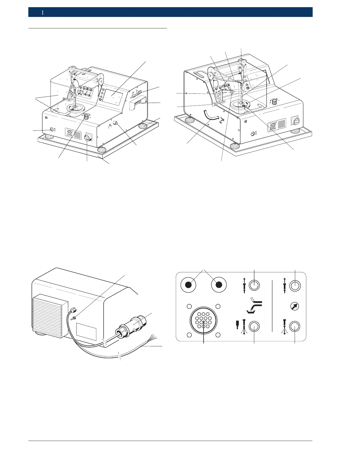
3.5 Description of unit
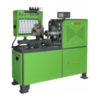
3.5.1 Front view
458822
EPS200
1l
BOSCH
X20
2
3
4
5
7
8
9
Fig. 1: Front view
1 LCD display with touchscreen
2 Stylus
3 PC connections
4 Foot (height adjustable)
5 Connection for external extractor
6 Oil collecting trough
7 Master switch (with emergency stop function)
8 Extraction controller for internal extractor
9 Oil level display
10 Protective cover with handle
3.5.2 Rear view
458822/1Ko
1
2
3
Fig. 2: Rear view
1 Connection for compressed air
2 Connector for three-phase current (400 V)
3 Electrical connecting cable for three-phase current (200 V)
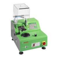
3.5.3 Components for testing
EPS 200
1l
BOSCH
458822-11
1
9
8
5
3
2
X20
Fig. 3: Components for testing
1 CRI/CRIN or DHK/UI
2 Jet chamber
3 Injection chamber
4 Clamping screw for securing the CRI/CRIN or DHK/UI
5 Flushing drain
6 Clamping screw for tool holder height adjustment
7 Tool holder
8 Connector panel
9 High pressure connecting line for test oil supply
10 Connection adapter for CRI/CRIN and DHK/UI
3.5.4 Connector panel
X20
458822-81
Fig. 4: Connector panel
1 Connecting cables for emergency shutdown
2 Flushing connection for CRI/CRIN (return)
*)
3 Test connection for CRI/CRIN (return)
4 Test connection for CRI/CRIN (injection)
5 Flushing connection and test connection for DHK/UI;
Flushing connection for CRI/CRIN (injection)
*)
6 Electrical connecting socket for CRI/CRIN
*)
The flushing connection for CRI/CRIN (return and injection)
currently has no function. It is designed for any later
enhancements of the system.
 Loading...