70 Sync Scorer Components
(10) Board Address 2
Switches 1,2,3,4,5,6,7 - Not used
Switch 8 - Set to the “ON” position.
(11) Ball Detect (JP17) - This setting is only impacts installations that use cameras for scoring.
(Centers without GS-Series pinsetters and StringPin pinsetters)
CAUTION! The ball detect jumper on the Distribution board MUST be set to
the proper voltage. Failure to do so can cause permanent damage to the ball
detector.
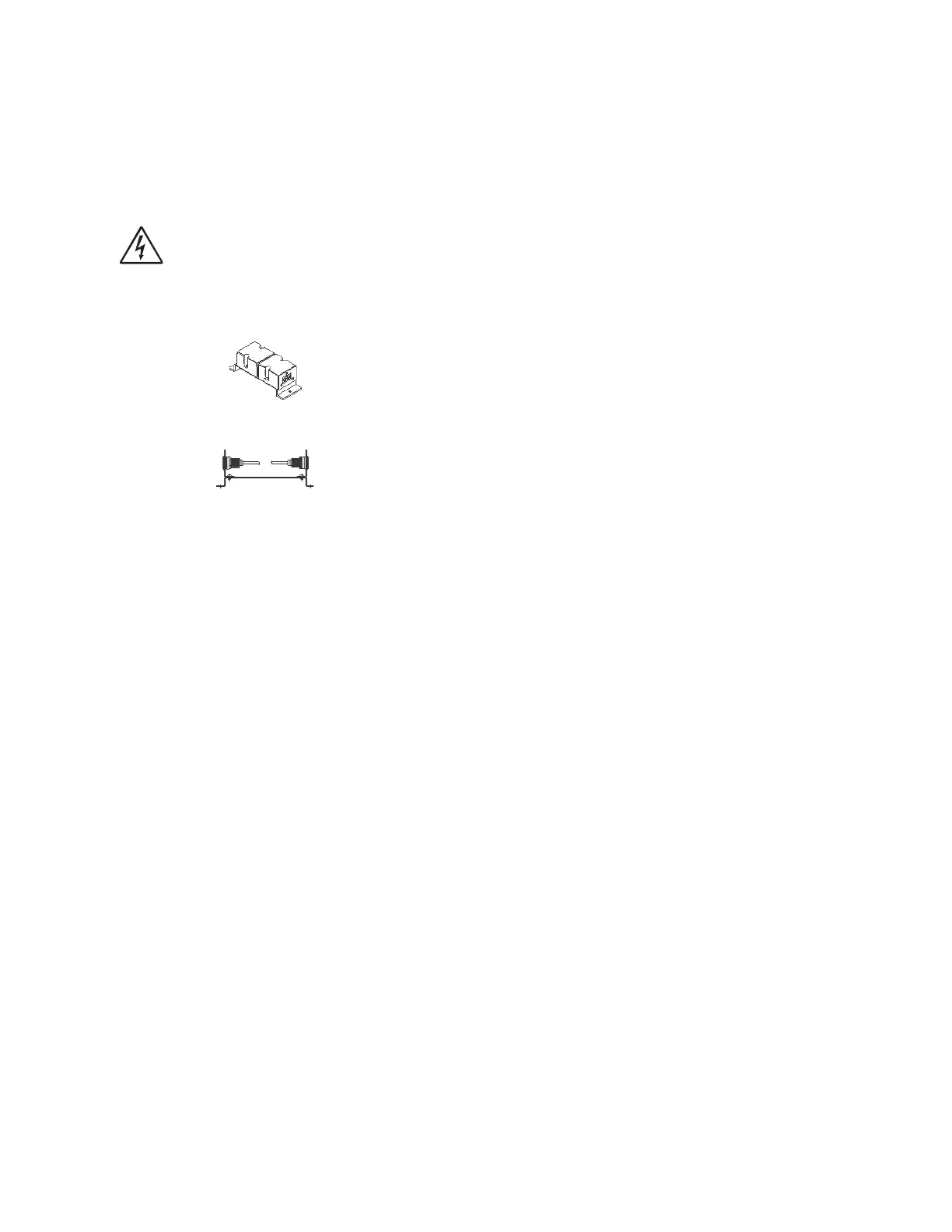
Square Ball Detector - Install jumper at pins 1-2 (5V)
Round Ball Detector - Install jumper at pins 2-3 (12V)
(12) Foul (JP18)
Brunswick Foul Unit - Install jumper (Default)
AMF Foul Unit - Remove Jumper
(13) LAN3 Communication Type (JP20) - Determines the communication protocol used for
LAN3 (J18).
Default - Install jumper at pins 2-3 (RS232)
Intellishield controller connected to LAN3 - Install jumper at pins 1-2 (RS485)