Menu 5
Parameter
structure
Keypad and
display
Parameter
x.00
Parameter
description format
Advanced parameter
descriptions
Macros
Serial comms
protocol
Electronic
nameplate
Performance
Feature look-
up table
102 Unidrive SP Advanced User Guide
www.controltechniques.com Issue Number: 7
Closed-loop vector and Servo
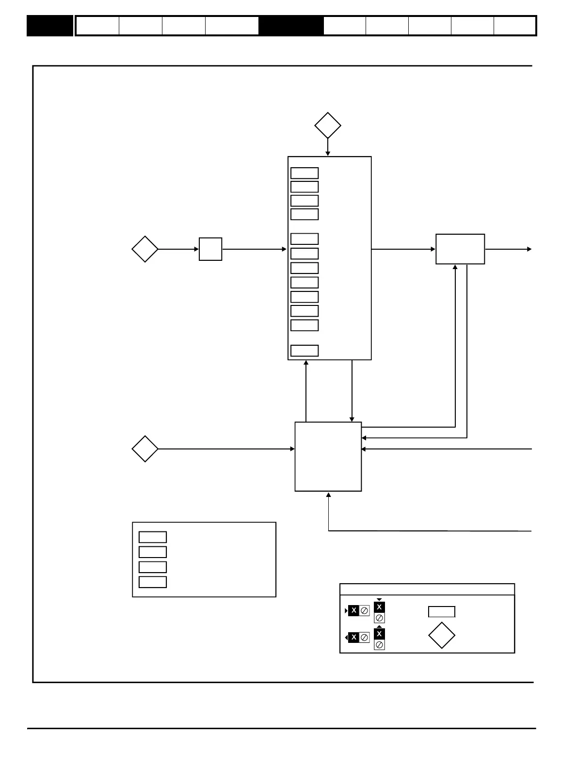
Figure 5-11 Menu 5 Closed-loop logic diagram
3.04
Closed-Loop Vector
3.25
Encoder phase
angle
5.06
Motor rated
frequency
5.08
Motor full load
rated speed
5.09
Motor rated
voltage
5.10
Motor rated
power factor
5.07
Motor rated
current
5.11
Motor number
of poles
5.17
Motor stator
resistance
5.24
Motor transient
inductance
5.25
Motor stator
inductance
5.29
Motor saturation
break-point 1
5.30
Motor saturation
break-point 2
Servo
Flux Calculator
Current limits
Current control
Overload detection
Current loop gains
Torque reference
Current demand filter
Menu 4
Reference
frame
transformation
3.02
Speed
feedback
Speed-loop
controller
output
Position
feedback
Flux
magnitude
Current
references
Current
feedback
5.01
Flux angle
5.12
5.15
5.26
5.31
Auto-tune
Low frequency voltage boost
High dynamic performance enable
Voltage controller gain
0.XX
0.XX
Key
Read-write (RW)
parameter
Read-only (RO)
parameter
Input
terminals
Output
terminals
The parameters are all shown at their default settings
∫
http://nicontrols.com