Parameter
structure
Keypad and
display
Parameter
x.00
Parameter
description format
Advanced parameter
descriptions
Macros
Serial comms
protocol
Electronic
nameplate
Performance
Feature look-
up table
Menu 5
Unidrive SP Advanced User Guide 113
Issue Number: 7 www.controltechniques.com
Open-loop, Closed-loop vector and Servo
The auto-tune tests may be aborted by removing the run command or the enable or if a trip occurs. During the auto-tune tests the following trips can
occur in addition to the other drive trips.
*The rS trip is produced if the drive cannot achieve the necessary current levels to measure the stator resistance during the test (i.e. there is no motor
connected to the drive), or if the necessary current level can be achieved, but the calculated resistance exceeds the maximum values for the
particular drive size or it exceeds 30.000Ω. The maximum measurable value for a particular drive size can be calculated from the following formula.
Rs
max
= DC_VOLTAGE_MAX / Drive rated current / 0.45 / √2
If a tuneX or tune trip occurs in servo mode, the trip cannot be reset unless the drive is disabled either via the hardware enable input of the user
enable (Pr 06.15) or the control word (Pr 6.42, Pr 6.43).
Open-loop
Setting this bit enables dynamic V to f mode which is intended for applications where power loss should be kept to a minimum under low load
conditions. The rated frequency used to derive the voltage to frequency characteristic of the drive is varied with load:
if |active current| < 0.7 x rated active current
motor rated frequency = Pr 5.06 x (2 - (active current / (0.7 x rated active current)))
else if |active current| ≥ 0.7 x rated active current
motor rated frequency = Pr 5.06
Although the rated frequency varies the value shown as Pr 5.06 does not vary from that set by the user.
Closed-loop vector
At light load the losses in the motor can be reduced by reducing the motor flux. When flux optimisation is selected the flux producing current in the
motor is reduced under light load conditions so that it is equal to the torque producing current with a minimum limit of half the rated flux producing
current. This optimises the copper losses in the motor and reduces the iron losses.
Trip code Reason Test which can cause trip
tunE1
The position feedback did not change
(i.e. motor did not turn or feedback failed)
Closed-loop vector 2
Servo 1,2,5
The motor did not reach the required speed
Closed-loop vector 3
Servo 3
tunE2
Position feedback direction incorrect
Closed-loop vector 2
Servo 1,2
The motor could not be stopped
Closed-loop vector 3
Servo 3
Minimal movement phasing test failed Servo 5
tunE3
Drive encoder commutation signals connected
incorrectly, i.e. direction incorrect.
(Drive encoder only.)
Servo 1,2
The motor was moving when the minimal movement
phasing test was initiated
Servo 5
The calculated inertia is out of range
Closed-loop vector 3
Servo 3
tunE4
Drive encoder U commutation signal fail
(Drive encoder only.)
Servo 1,2
tunE5
Drive encoder V commutation signal fail
(Drive encoder only.)
Servo 1,2
tunE6
Drive encoder W commutation signal fail
(Drive encoder only.)
Servo 1,2
tunE7
Motor poles set-up incorrectly
This trip may also occur if the encoder lines parameter
is incorrect. This trip will not occur if the motor poles
are more than 12.
Closed-loop vector 2
Servo 1,2
tunE Auto-tune stopped before completion All
rS* Stator resistance too high
Open-loop 1, 2
Closed-loop vector 1
Servo 2
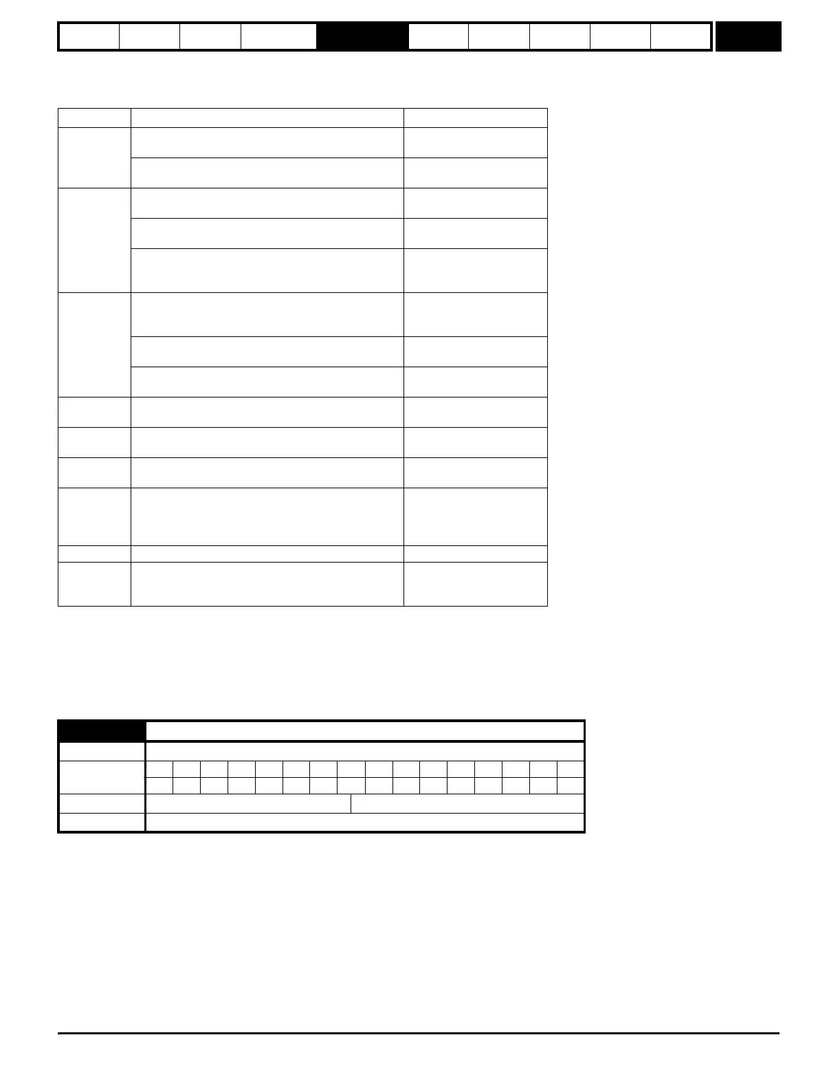
5.13 Dynamic V to F / flux optimise select
Drive modes Open-loop, Closed-loop vector
Coding
Bit SP FI DE Txt VM DP ND RA NC NV PT US RW BU PS
111
Default Open-loop, Closed-loop vector 0
Update rate Background read
http://nicontrols.com