Parameter
structure
Keypad and
display
Parameter
x.00
Parameter
description format
Advanced parameter
descriptions
Macros
Serial comms
protocol
Electronic
nameplate
Performance
Feature look-
up table
Menus 15 to 17
SM-I/O Plus
Unidrive SP Advanced User Guide 263
Issue Number: 7 www.controltechniques.com
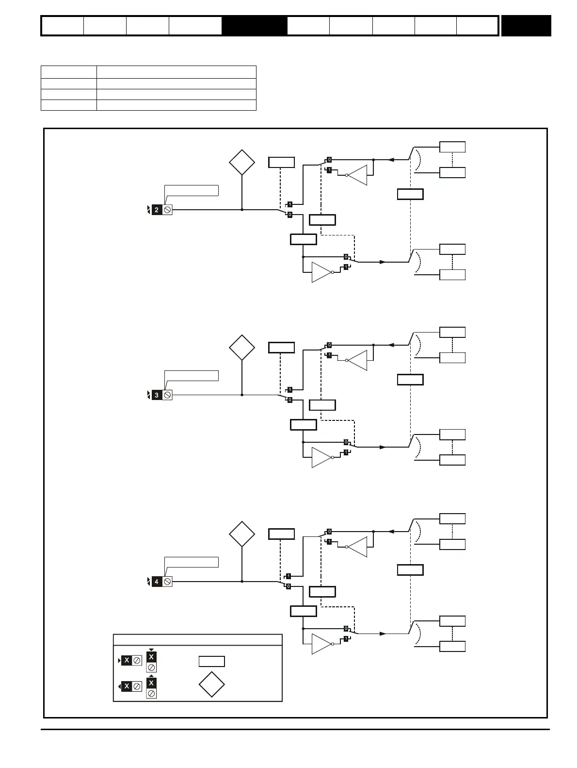
5.16.4 SM I/O Plus
Possible Solutions Module error status values
Figure 5-29 SM I/O Plus Digital Input/Output logic diagram 1
Error code Reason for fault
0 No errors
1 Digital output short circuit
74 Module over-temperature
.33
??.??
Any
unprotected
bit
parameter
??.??
??.??
Any bit
parameter
??.??
.23
x(-1)
x(-1)
.13
X.03
X.32
??.??
Any
unprotected
bit
parameter
??.??
??.??
??.??
Any bit
parameter
.22
x(-1)
x(-1)
.12
X.10
T2 digital I/O 1
T2 digital
I/O 1 state
X.31
T2 output
select
??.??
??.??
Any
unprotected
bit paramete
??.??
??.??
Any bit
parameter
X.21
T2 digital I/O
1 destination
/ source
x(-1)
x(-1)
X.11
T2 digital
I/O 1 invert
X.09
X.29
Positive
logic select
0.XX
0.XX
Key
Read-write (RW)
parameter
Read-only (RO)
parameter
Input
terminals
Output
terminals
The parameters are all shown at their default settin
T3 digital I/O 2
T3 digital
I/O 2 state
T3 output
select
T3 digital I/O
2 destination
/ source
T3 digital
I/O 2 invert
T4 digital I/O 3
T4 digital
I/O 3 state
T4 output
select
T4 digital I/O
3 destination
/ source
T4 digital
I/O 3 invert
.29
Positive
logic select
.29
Positive
logic select
http://nicontrols.com