Menus 15 to 17
SM-Uni Enc Pl
Parameter
structure
Keypad and
display
Parameter
x.00
Parameter
description format
Advanced parameter
descriptions
Macros
Serial comms
protocol
Electronic
nameplate
Performance
Feature look-
up table
230 Unidrive SP Advanced User Guide
www.controltechniques.com Issue Number: 7
The marker flag is set each time the marker input becomes active, but it is not reset by the drive, and so this must be done by the user. The marker
function only operates when Ab, Fd, Fr, Ab.Servo, Fd.Servo, Fr.Servo type encoders are selected with Pr x.15.
When an encoder without comms is used it is sometimes desirable to mask off the most significant bits of the revolution counter. Normally this would
be required with an absolute multi-turn encoder where the number of turns measured is less than 65,536. If Pr x.09 is zero the revolution counter (Pr
x.04) is held at zero. If Pr x.09 has any other value it defines the maximum number of the revolution counter before it is reset to zero. For example, if
Pr x.09 = 5, then Pr x.04 counts up to 31 before being reset.
When an encoder with comms is used, Pr x.09 must contain the number of bits in the comms message used to give the multi-turn information. For a
single turn comms encoder, Pr x.09 must be set to zero. It is possible for the drive to set up this parameter automatically from information obtained
from the encoder via HIPERFACE or EnDat interfaces (see Pr x.18 on page 234).
When Ab, Fd, Fr, Ab.Servo, Fd.Servo, Fr.Servo or SINCOS signals are used the equivalent number of encoder lines per revolution must be set-up
correctly in Pr x.10 to give the correct speed and position feedback. This is particularly important if the encoder is selected for speed feedback with Pr
3.26. The equivalent number of encoder lines per revolution (ELPR) is defined as follows:
For Ab, Fd, Fr, Ab.Servo, Fd.Servo and Fr.Servo encoders the incremental (A/B) signal frequency should not exceed 500kHz.
For SC.Hiper, SC.EnDat, SC and SC.SSI encoders the sine wave signal frequency can be up to 166kHz, but the resolution is reduced at higher
frequencies. The table below shows the number of bits of interpolated information at different frequencies and with different voltage levels at the drive
encoder port. The total resolution in bits per revolution is the ELPR plus the number of bits of interpolated information.
Where encoder comms alone is used as position feedback, the equivalent lines per revolution (Pr x.10) is not used in setting up the encoder interface.
It is possible for the drive to set up this parameter automatically from information obtained from the encoder via HIPERFACE or EnDat interfaces (see
Pr x.18 on page 234).
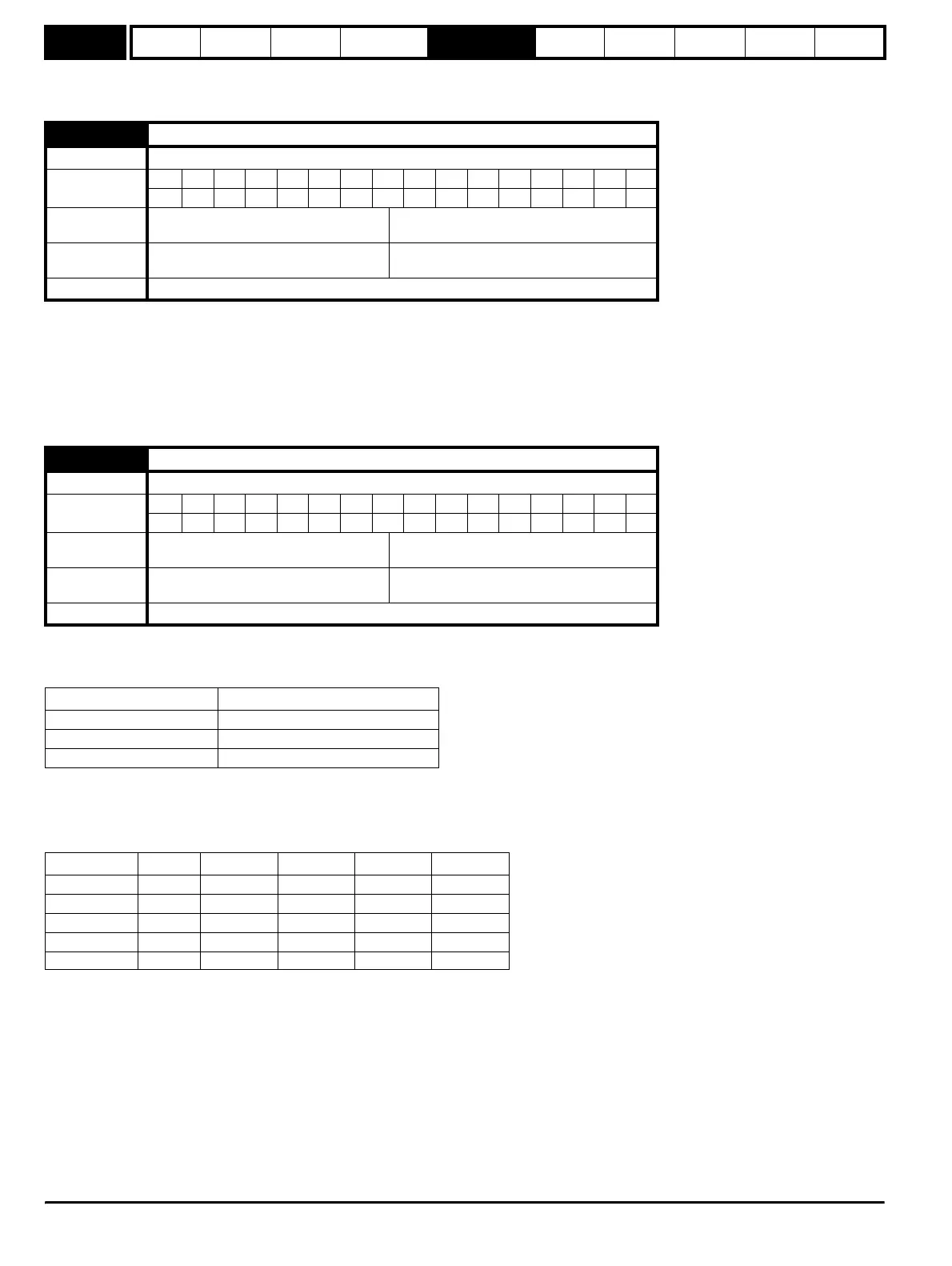
x.09 Encoder turns
Drive modes Open-loop, Closed-loop vector, Servo, Regen
Coding
Bit SP FI DE Txt VM DP ND RA NC NV PT US RW BU PS
111
Range
Open-loop, Closed-loop vector, Servo,
Regen
2
x
0 ≤ x ≤ 16
Default
Open-loop, Closed-loop vector, Servo,
Regen
2
16
(65,536)
Update rate Background read
x.10 Equivalent lines per revolution
Drive modes Open-loop, Closed-loop vector, Servo, Regen
Coding
Bit SP FI DE Txt VM DP ND RA NC NV PT US RW BU PS
111
Range
Open-loop, Closed-loop vector, Servo,
Regen
0 to 50,000
Default
Open-loop, Closed-loop vector, Servo,
Regen
4,096
Update rate Background read
Position feedback device ELPR
Ab, Ab.Servo number of lines per revolution
Fd, Fr, Fd.Servo, Fr.Servo number of lines per revolution / 2
SC.Hiper, SC.EnDat, SC number of sine waves per revolution
Volt/Freq 1,000 5,000 50,000 100,000 150,000
1.2 11 11 11 10 10
1.0 11 11 10 10 9
0.810101010 9
0.6 10 10 10 9 9
0.499998
http://nicontrols.com