Parameter
structure
Keypad and
display
Parameter
x.00
Parameter
description format
Advanced parameter
descriptions
Macros
Serial comms
protocol
Electronic
nameplate
Performance
Feature look-
up table
Menu 6
Unidrive SP Advanced User Guide 123
Issue Number: 7 www.controltechniques.com
Open-loop
Stopping is in two distinct phases: decelerating to stop, and stopped.
Once modes 3 or 4 have begun the drive must go through the ready state before being restarted either by stopping, tripping or being disabled.
Closed-loop vector and Servo
Only one stopping phase exists and the ready state is entered as soon as the single stopping action is complete.
The motor can be stopped with position orientation after stopping. This mode is selected with the position controller mode (Pr 13.10). When this mode
is selected Pr 6.01 has no effect.
0: dis
There is no mains loss detection and the drive operates normally only as long as the DC bus voltage remains within specification (i.e. >Vuu). Once
the voltage falls below Vuu a UU trip occurs and this will reset itself if the voltage rises again above VuuRestart shown in the table below.
1: Stop
Open-loop
The action taken by the drive is the same as for ride through mode, except the ramp down rate is at least as fast as the deceleration ramp setting and
the drive will continue to decelerate and stop even if the mains is re-applied. If normal or timed injection braking is selected the drive will use ramp
mode to stop on loss of the supply. If ramp stop followed by injection braking is selected, the drive will ramp to a stop and then attempt to apply DC
injection. At this point, unless the mains has been restored, the drive is likely to initiate a UU trip.
Closed-loop vector or Servo
The speed reference is set to zero and the ramps are disabled allowing the drive to decelerate the motor to a stop under current limit. If the mains is
re-applied while the motor is stopping any run signal is ignored until the motor has stopped. If the current limit value is set at a very low level the drive
may trip UU before the motor has stopped.
2: ride.th
The drive detects mains loss when the DC bus voltage falls below Vml
1
. The drive then enters a mode where a closed-loop controller attempts to hold
the DC bus level at Vml
2
. This causes the motor to decelerate at a rate that increases as the speed falls. If the mains is re-applied it will force the DC
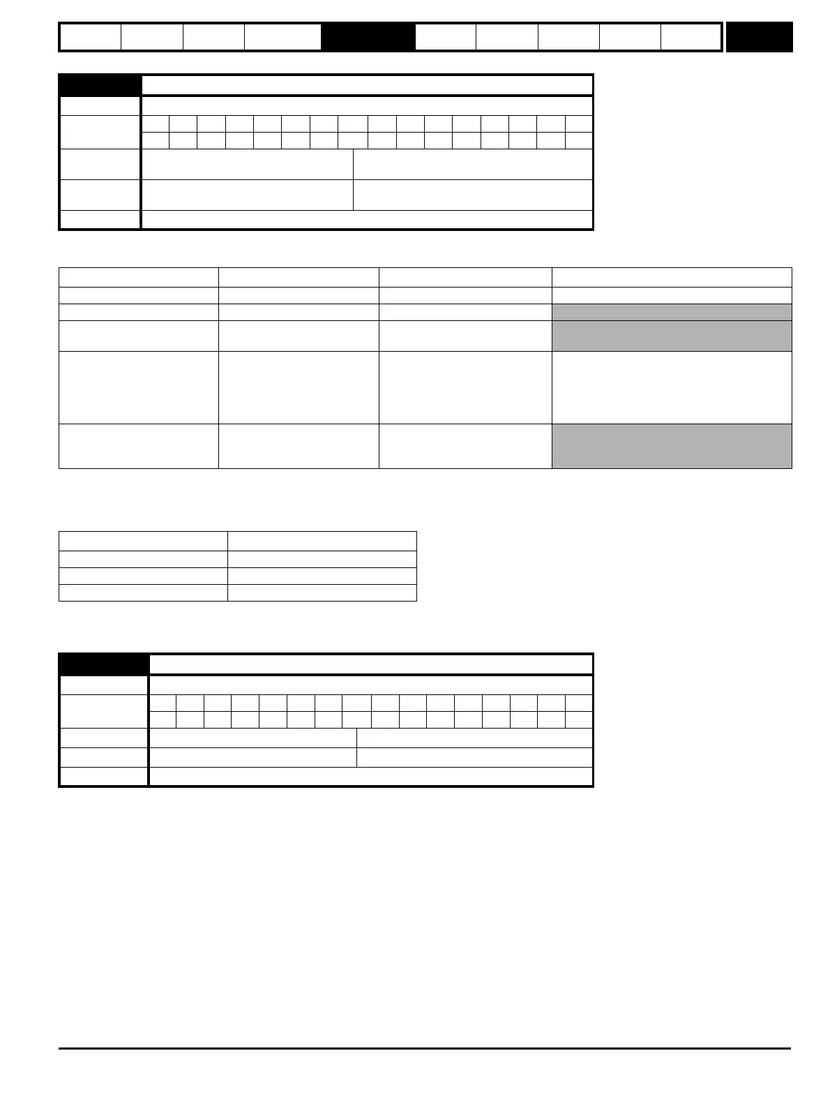
6.01 Stop mode
Drive modes Open-loop, Closed-loop vector, Servo
Coding
Bit SP FI DE TE VM DP ND RA NC NV PT US RW BU PS
1111
Range
Open-loop
Closed-loop vector, Servo
0 to 4
0 to 2
Default
Open-loop, Closed-loop vector
Servo
1
2
Update rate Background read
Stopping Mode Phase 1 Phase 2 Comments
0: Coast Inverter disabled Drive cannot be re-enabled for 1s Delay in phase 2 allows rotor flux to decay.
1: Ramp Ramp down to zero frequency Wait for 1s with inverter enabled
2: Ramp followed by DC
injection
Ramp down to zero frequency
Inject DC at level specified by Pr
6.06 for time defined by Pr 6.07
3: DC injection with zero
speed detection
Low frequency current
injection with detection of low
speed before next phase.
Inject DC at level specified by Pr
6.06 for time defined by Pr 6.07
The drive automatically senses low speed and
therefore it adjusts the injection time to suit the
application. If the injection current level is too
small the drive will not sense low speed
(normally a minimum of 50-60% is required).
4: Timed DC injection braking
stop
Inject DC at level specified by
Pr 6.06 for time specified by Pr
6.07.
No phase 2.
Stopping Mode Action
0: Coast Inhibits the inverter
1: Ramp Stop with ramp
2: No ramp Stop with no ramp
6.03 Mains loss mode
Drive modes Open-loop, Closed-loop vector, Servo
Coding
Bit SP FI DE TE VM DP ND RA NC NV PT US RW BU PS
1111
Range Open-loop, Closed-loop vector, Servo 0 to 2
Default Open-loop, Closed-loop vector, Servo 0
Update rate Background read
http://nicontrols.com