Parameter
structure
Keypad and
display
Parameter
x.00
Parameter
description format
Advanced parameter
descriptions
Macros
Serial comms
protocol
Electronic
nameplate
Performance
Feature look-
up table
Menu 3
Regen
Unidrive SP Advanced User Guide 75
Issue Number: 7 www.controltechniques.com
Parameter descriptions: Regen
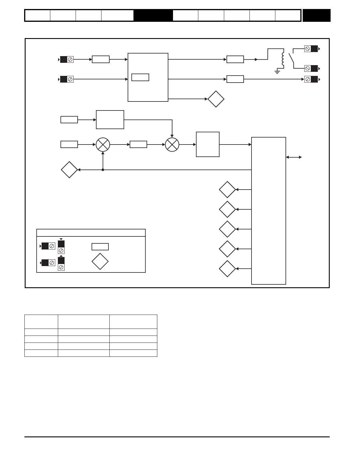
Figure 5-5 Menu 3 Regen logic diagram
In Regen mode the drive assumes the mains is lost and does cannot close the input and does not attempt synchronisation if the DC bus voltage is
below the levels given in the table below. If the unit is synchronised and the DC bus voltage falls below this level the unit is disabled and the input
contactor is opened. The Regen unit also monitors the voltage at its AC terminals for mains loss and if this falls below the levels given in the table the
unit is disabled and the input contactor is opened.
Voltage
rating
DC voltage mains
loss detection level
AC voltage mains
loss detection level
200V 205Vdc 75Vac
400V 410Vdc 150Vac
575V 540Vdc 225Vac
690V 540Vdc 225Vac
2.01
Output
voltage
5.02
2.01
Output
power
5.03
2.01
Reactive
power
3.01
2.01
Output
frequency
5.01
2.01
Input
inductance
3.02
Modulator
and power
circuit
2.01
DC bus
voltage
5.05
3.05
Voltage
set-point
3.06
Current
control
(Menu 4)
Voltage
controller
kp gain
Mains
supply
3.10
Power
feed-forward
compensation
Power to
current
conversion
0.XX
0.XX
Key
Read-write (RW)
parameter
Read-only (RO)
parameter
Input
terminals
Output
terminals
X
X
X
X
The parameters are all shown at their default settings
Enable
input
Regen
sequencer
3.08
o
tstart
contactor
closed
3.04
Regen
restart
mode
2.013.03
Regen
status
3.07
3.09
Close soft
start contactor
Enable
motor drive
25
31
24
+
+
+
_
41
42
http://nicontrols.com