Parameter
structure
Keypad and
display
Parameter
x.00
Parameter
description format
Advanced parameter
descriptions
Macros
Serial comms
protocol
Electronic
nameplate
Performance
Feature look-
up table
Menu 6
Unidrive SP Advanced User Guide 133
Issue Number: 7 www.controltechniques.com
UNISP1xxx, UNISP2xxx, UNISP3xxx:
The drive is using the low voltage auxiliary power input to derive the power circuit supplies (i.e. gate drives, fans, etc.). The main power terminals can
be connected to a different supply of any voltage up to the maximum normal supply level. All parameters voltage based parameters are calculated
from the auxiliary supply level and not the supply from the main power terminals. If the auxiliary supply and the main supply are different then these
parameters will not be correct. Parameters that are saved at power-down are not saved when the power is removed in this mode.
Frame sizes 4, 5, 6 and 7:
The drive is using the battery mode enable input to derive the power circuit supplies (i.e. gate drives, fans, etc.) A low voltage d.c. supply is connected
to the d.c. power terminals. All parameters that are calculated based on voltage are derived from the voltage connected to the power terminals.
Parameters that are saved at power-down are not saved when the power is removed in this mode.
For all sizes of drive in low voltage battery mode, 24V must also be supplied via the 24V control board power supply input. The drive will operate
normally except that mains loss detection is disabled, the braking IGBT will only operate when the drive is enabled, and the voltage levels contained
in the following table are used instead of the normal high voltage levels whatever the voltage rating of the drive.
Full scale voltage measurement and the over voltage trip level are defined by DC_VOLTAGE_MAX. However, the maximum level of the low voltage
battery supply voltage should not normally exceed 90% of this value to avoid spurious over voltage trips.
The drive thermal model system normally controls the fan speed, however the fan can be forced to operate at full speed if this parameter is set to 1.
When this is set to 1 the fan remains at full speed until 10s after this parameter is set to zero.
This parameter defines the nominal supply voltage when operating in low voltage mode. The parameter is used to define the braking IGBT switching
threshold and the over voltage trip level for low voltage battery mode (see Pr 6.44).
When the drive is used in any of the motor control modes (not regen mode), phase loss, supply imbalance or complete supply loss are detected by
monitoring the d.c. link voltage. When power modules are connected in parallel (i.e. a multi-module drive) mains loss or phase loss is also detected by
the input rectifier within each of the power modules. If all input stages detect mains loss then the d.c. link voltage level can be used to initiate the
appropriate action, i.e. main loss ride through. If mains loss is detected by some, but not all the input stages the drive will initiate an ACUU.P trip
because the remaining active input stages could be overloaded. If all input stages detect phase loss then the d.c. link voltage ripple can be used to
detect the phase loss / imbalance condition at which the drive should stop the motor and produce a PH trip. If phase loss is detected by some, but not
all the input stages the drive will initiate a PH.P trip because the input stages with a missing phase or excessive phase imbalance could be running in
a condition that would cause their power devices to overheat.
If a drive is operating in regen mode or from a low voltage battery supply detection of mains or phase loss from the input power stages is automatically
disabled because the a.c. input system is not active. If the drive is operating from a high voltage d.c. supply and is a multi-module drive mains loss
Voltage level
DC_VOLTAGE_MAX Pr 6.46 x 1.45
Braking IGBT threshold voltage Pr 6.46 x 1.325
Under voltage trip level 36V
Restart voltage level after UU trip 40V
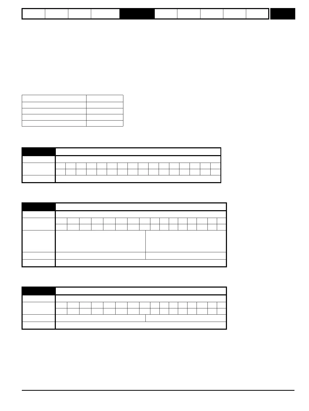
6.45 Force cooling fan to run at full speed
Drive modes Open-loop, Closed-loop vector, Servo, Regen
Coding
Bit SP FI DETEVMDPNDRANCNVPTUSRWBUPS
111
Update rate Background read
6.46 Nominal low voltage battery supply
Drive modes Open-loop, Closed-loop vector, Servo, Regen
Coding
Bit SP FI DE TE VM DP ND RA NC NV PT US RW BU PS
1111
Range
48 to 48 for UNISP1xxx drives
48 to 72 for UNISP2xxx and UNISP3xxx drives
48 to 72 for all other 200V drives
48 to 96 for all other 400V and 690V drives
Default Open-loop, Closed-loop vector, Servo, Regen 48
Update rate Background read
6.47 Disable mains/phase loss detection from input rectifier
Drive modes Open-loop, Closed-loop vector, Servo
Coding
Bit SP FI DE TE VM DP ND RA NC NV PT US RW BU PS
111
Default Open-loop, Closed-loop vector, Servo 0
Update rate Background read
http://nicontrols.com