Parameter
structure
Keypad and
display
Parameter
x.00
Parameter
description format
Advanced parameter
descriptions
Macros
Serial comms
protocol
Electronic
nameplate
Performance
Feature look-
up table
Menus 15 to 17
SM-Uni Enc Pl
Unidrive SP Advanced User Guide 241
Issue Number: 7 www.controltechniques.com
If Pr x.44 is zero the drive can check the position derived with the sine and cosine waveforms from a SinCos encoder via serial communications. If Pr
x.44 is set to one the checking is disabled and encoder comms is available via the transmit and receive registers. The transmission system can be
used to communicate with encoders provided the mode is SC.Hiper or SC.Endat as follows:
For both comms protocols more than one byte of data must be written to the transmit register or read from the receive register during the transfer of
one message. Bit 13-15 are used to indicate the following:
Data should be written to the transmit buffer when the buffer has been reset to zero by the module. The data will be transferred to the comms buffer
and the transmit register will be cleared. Data can be read from the receive buffer at any time. If there is receive data in the buffer bit 15 will be set.
Once the data has been read the buffer should be cleared and the module will then transfer more data. The buffer is 16 bytes long and any messages
that exceed this length (including the checksum added for HIPERFACE) will cause an error. The status flags are defined as follows:
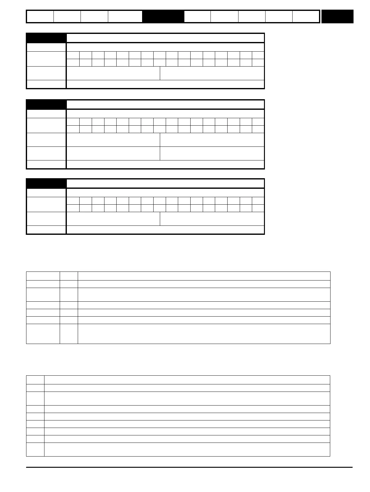
x.42 Encoder comms transmit register
Drive modes Open-loop, Closed-loop vector, Servo, Regen
Coding
Bit SP FI DE Txt VM DP ND RA NC NV PT US RW BU PS
111
Range
Open-loop, Closed-loop vector, Servo,
Regen
0 to 65,535
Update rate Background read
x.43 Encoder comms receive register
Drive modes Open-loop, Closed-loop vector, Servo, Regen
Coding
Bit SP FI DE Txt VM DP ND RA NC NV PT US RW BU PS
111
Range
Open-loop, Closed-loop vector, Servo,
Regen
0 to 65,535
Default
Open-loop, Closed-loop vector, Servo,
Regen
0
Update rate Background write
x.44 Disable encoder position check
Drive modes Open-loop, Closed-loop vector, Servo, Regen
Coding
Bit SP FI DE Txt VM DP ND RA NC NV PT US RW BU PS
111
Default
Open-loop, Closed-loop vector, Servo,
Regen
0
Update rate Background read
Register Bit Function
Transmit 15 Must be set for the Solutions Module to transfer the LS byte to the comms buffer.
Transmit 14
The LS byte is the last byte of the message and this byte should be put in the comms buffer and be transferred
to the encoder.
Transmit 13 The LS byte is the first byte of the message. (If this is used the buffer pointer is reset to the start of the buffer.)
Receive 15 Indicates data from the last transfer can be read from the receive buffer.
Receive 14 The byte in the LS byte is the last byte of the receive message
Receive 13
There is no data in the receive buffer and the LS byte is the comms system status. If there was an error in the
received message this will always be set and one of the status error bits will be set until the comms is used again
by this system.
Bit Meaning
0 The number of bytes put into the transmit buffer is not consistent with the expected message length.
1
The number of bytes written to the transmit buffer, or the expected length of the store data transmit message, or the expected
length of a read data message have exceed the length of the buffer.
2 The command code is not supported.
3 The encoder has signalled an error.
4 There was an error in the checksum/CRC of the received message.
5 A time-out occurred.
6 The last message was to auto-configure the drive encoder and the encoder was identified successfully.
7
The last message was initiated through the Solutions Module interface or from the drive electronic nameplate system and the
last message was successful.
http://nicontrols.com