Menu 7
Parameter
structure
Keypad and
display
Parameter
x.00
Parameter
description format
Advanced parameter
descriptions
Macros
Serial comms
protocol
Electronic
nameplate
Performance
Feature look-
up table
144 Unidrive SP Advanced User Guide
www.controltechniques.com Issue Number: 7
The IGBT junction temperature is calculated using Stack 1 temperature (Pr 7.04) and a thermal model of the drive power stage. The resulting
temperature is displayed in this parameter. The calculated IGBT junction temperature is used to modify the drive switching frequency to reduce losses
if the devices become too hot (see Pr 5.18 on page 115).
In addition to monitoring the IGBT junction temperatures the drive includes a thermal protection system to protect the other components within the
drive. This includes the effects of drive output current and DC bus ripple. The estimated temperature is displayed as a percentage of the trip level in
this parameter. If the parameter value reaches 100% an Oht3 trip is initiated.
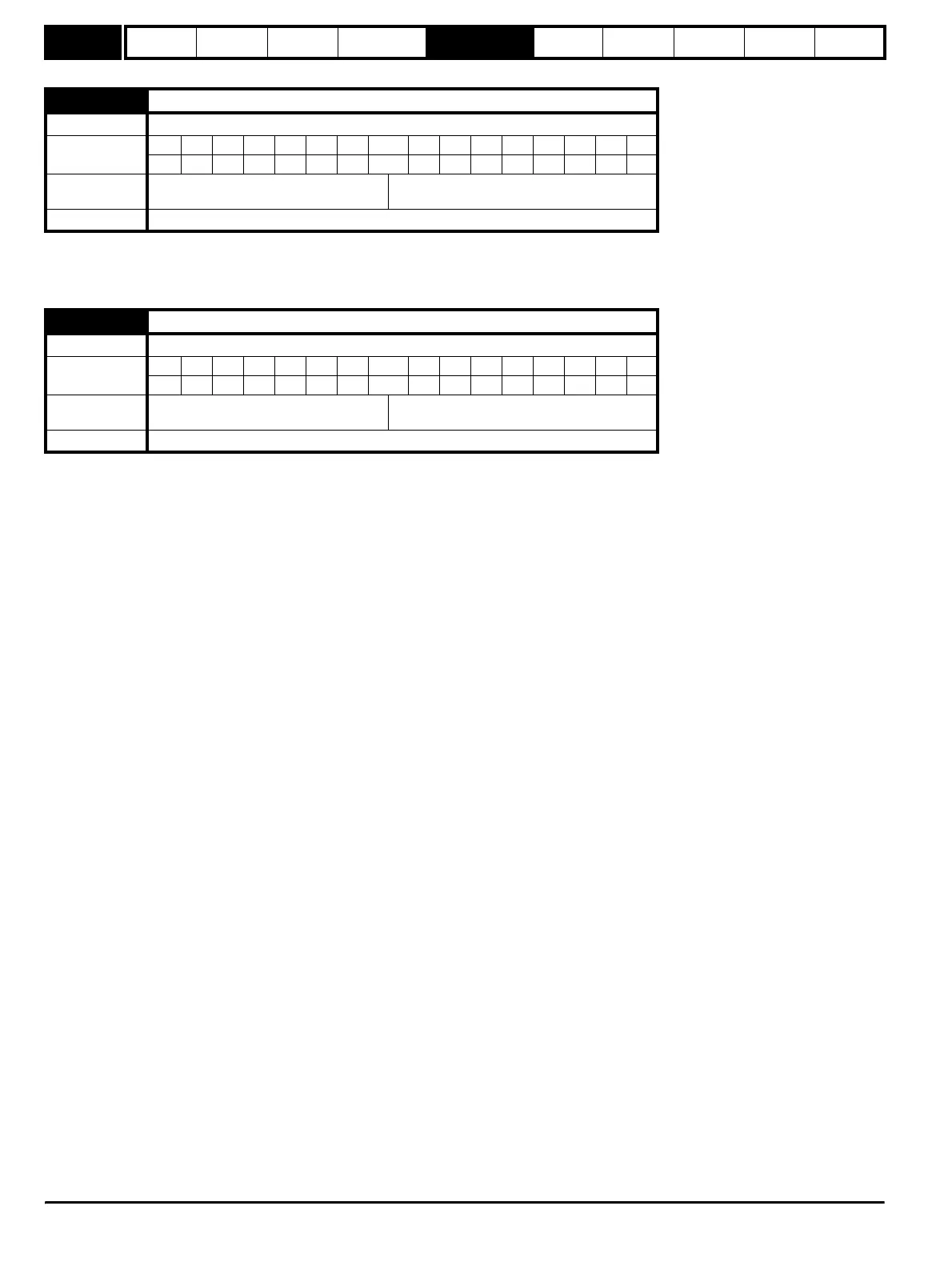
7.34 IGBT junction temperature
Drive modes Open-loop, Closed-loop vector, Servo, Regen
Coding
Bit SP FI DE Txt VM DP ND RA NC NV PT US RW BU PS
111
Range
Open-loop, Closed-loop vector, Servo,
Regen
±200 °C
Update rate Background write
7.35 Drive thermal protection accumulator
Drive modes Open-loop, Closed-loop vector, Servo, Regen
Coding
Bit SP FI DE Txt VM DP ND RA NC NV PT US RW BU PS
11 1 1 1
Range
Open-loop, Closed-loop vector, Servo,
Regen
0 to 100 %
Update rate Background write
http://nicontrols.com