Parameter
structure
Keypad and
display
Parameter
x.00
Parameter
description format
Advanced parameter
descriptions
Macros
Serial comms
protocol
Electronic
nameplate
Performance
Feature look-
up table
Menu 5
Unidrive SP Advanced User Guide 119
Issue Number: 7 www.controltechniques.com
When the flux in the motor is reduced below its rated level the level of torque producing current required for a given amount of shaft torque is higher
than the rated level. In speed control the compensation prevents gain reduction at higher speeds. In torque control the compensation maintains the
torque at the correct level for a given torque demand. In some applications using speed control it may be desirable to have a reduction of gain as the
motor flux is reduced to maintain stability. If this is required Pr 5.28 should be set to one. It should be noted that although field weakening is possible
in servo mode, gain compensation is not applied in this mode.
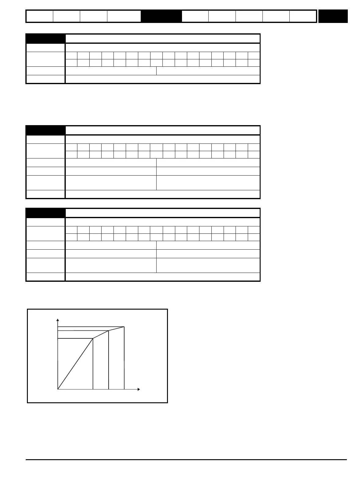
The rated level of flux in most induction motors causes saturation. Therefore the flux against flux producing current characteristic is non-linear. The
effects of saturation are to cause a step increase in torque when operating in torque mode as the speed increases into the field weakening region.
The drive can include the effects of saturation by representing the flux producing current to flux characteristic as a series of three lines as shown
below:
If Pr 5.29 and Pr 5.30 have their default values of 50 and 75, the characteristic becomes one line and there will be a linear relationship between the
drive estimate of flux and the flux producing current. If Pr 5.29 and Pr 5.30 are increased above 50 and 75 the drive estimate of flux can include the
effect of saturation. It is unlikely that information will be available to set up these parameters, and so the values are determined during the rotating
auto-tune test.
5.28 Field weakening compensation disable
Drive modes Closed-loop vector
Coding
Bit SP FI DE Txt VM DP ND RA NC NV PT US RW BU PS
111
Default Closed-loop vector 0
Update rate Background read
5.29 Motor saturation breakpoint 1
Drive modes Closed-loop vector
Coding
Bit SP FI DE Txt VM DP ND RA NC NV PT US RW BU PS
111
Range Closed-loop vector 0 to 100 % of rated flux
Default Closed-loop vector 50
Second motor
parameter
Closed-loop vector Pr 21.25
Update rate Background read
5.30 Motor saturation breakpoint 2
Drive modes Closed-loop vector
Coding
Bit SP FI DE Txt VM DP ND RA NC NV PT US RW BU PS
111
Range Closed-loop vector 0 to 100 % of rated flux
Default Closed-loop vector 75
Second motor
parameter
Closed-loop vector Pr 21.26
Update rate Background read
i_ma
%
lux
50 75 100
100%
Pr
5.30
Pr
5.29
http://nicontrols.com