Parameter
structure
Keypad and
display
Parameter
x.00
Parameter
description format
Advanced parameter
descriptions
Macros
Serial comms
protocol
Electronic
nameplate
Performance
Feature look-
up table
Menu 3
Closed-loop
Unidrive SP Advanced User Guide 57
Issue Number: 7 www.controltechniques.com
The user may enter the required speed controller gains into Pr 3.10 to Pr 3.15. However, if the load is predominantly a constant inertia and constant
torque, the drive can calculate the required Kp and Ki gains, provided a value of motor plus load inertia (Pr 3.18) and the motor torque per amp for
Servo mode (Pr 5.32) are set-up correctly. The gain values are calculated to give a required compliance angle or bandwidth. The calculated values for
Kp and Ki are written to Pr 3.10 and Pr 3.11 once per second when one of these set-up methods is selected (i.e. Pr 3.17 = 1 or 2). The values are
calculated from a linear model assuming a pure inertia load, not including the speed and current controller delays. The Kd gain is not affected. If
Pr 3.17 is set to 3 automatic gain set up is not active, but Kp is boosted by a factor of 16.
0: user set-up
With the default value the user should enter the required speed controller gains.
1: Bandwidth set-up
If bandwidth based set-up is required the following parameters must be set correctly: Pr 3.20 = required bandwidth, Pr 3.21 = required damping factor,
Pr 3.18 = motor + load inertia (it is possible to measure the load inertia as part of the auto-tuning process, see Pr 5.12 on page 109), Pr 5.32 = motor
torque per amp.
Ki = J / (Kc x Kt) x (2π x Bandwidth / Kbw)
2
= Pr 3.18 / (Rated drive current x Pr 5.32) x (2π x Pr 3.20 / Kbw)
2
Where: Kbw = √[ (2ξ
2
+ 1) +√((2ξ
2
+ 1)
2
+ 1) ]
Kp = 2 ξ √ [(Ki x J) / (Kc x Kt)] = 2 ξ √ [(Pr 3.11 x Pr 3.18) / (Rated drive current x Pr 5.32)]
2: Compliance angle set-up
If compliance angle based set-up is required the following parameters must be set correctly: Pr 3.19 = required compliance angle, Pr 3.21 = required
damping factor, Pr 3.18 = motor + load inertia (it is possible to measure the load inertia as part of the auto-tuning process, see Pr 5.12 on page 109),
Pr 5.24 = motor torque per amp.
Ki = 1 / Compliance angle (rad s
-1
)
Kp = 2 ξ √ [(Ki x J) / (Kc x Kt)] = 2 ξ √ [(Pr 3.11 x Pr 3.18) / (Rated drive current x Pr 5.32)]
3: Kp gain times 16
If this parameter is set to 3 the Kp gain (from whichever source) is multiplied by 16. This is intended to boost the range of Kp for applications with very
high inertia. It should be noted that if high values of Kp are used it is likely that the speed controller output will need to be filtered (see Pr 4.12) or the
speed feedback will need to be filtered (see Pr 3.42). If the feedback is not filtered it is possible the output of the speed controller will be a square
wave that changes between the current limits causing the integral term saturation system to malfunction.
The motor and load inertia represents the total inertia driven by the motor. This is used to set the speed controller gains (see Pr 3.13 on page 54) and
to provide torque feed-forwards during acceleration when required. (see Pr 4.11 on page 92) (It is possible to measure the inertia as part of the auto-
tune process, see Pr 5.12 on page 109.
The compliance angle is the required angular displacement when the drive delivers a torque producing current equivalent to the motor rated current
(Pr 5.07) with no field weakening. This parameter is used to define the compliance angle used for setting up the speed loop gain parameters
automatically when Pr 3.17 = 2.
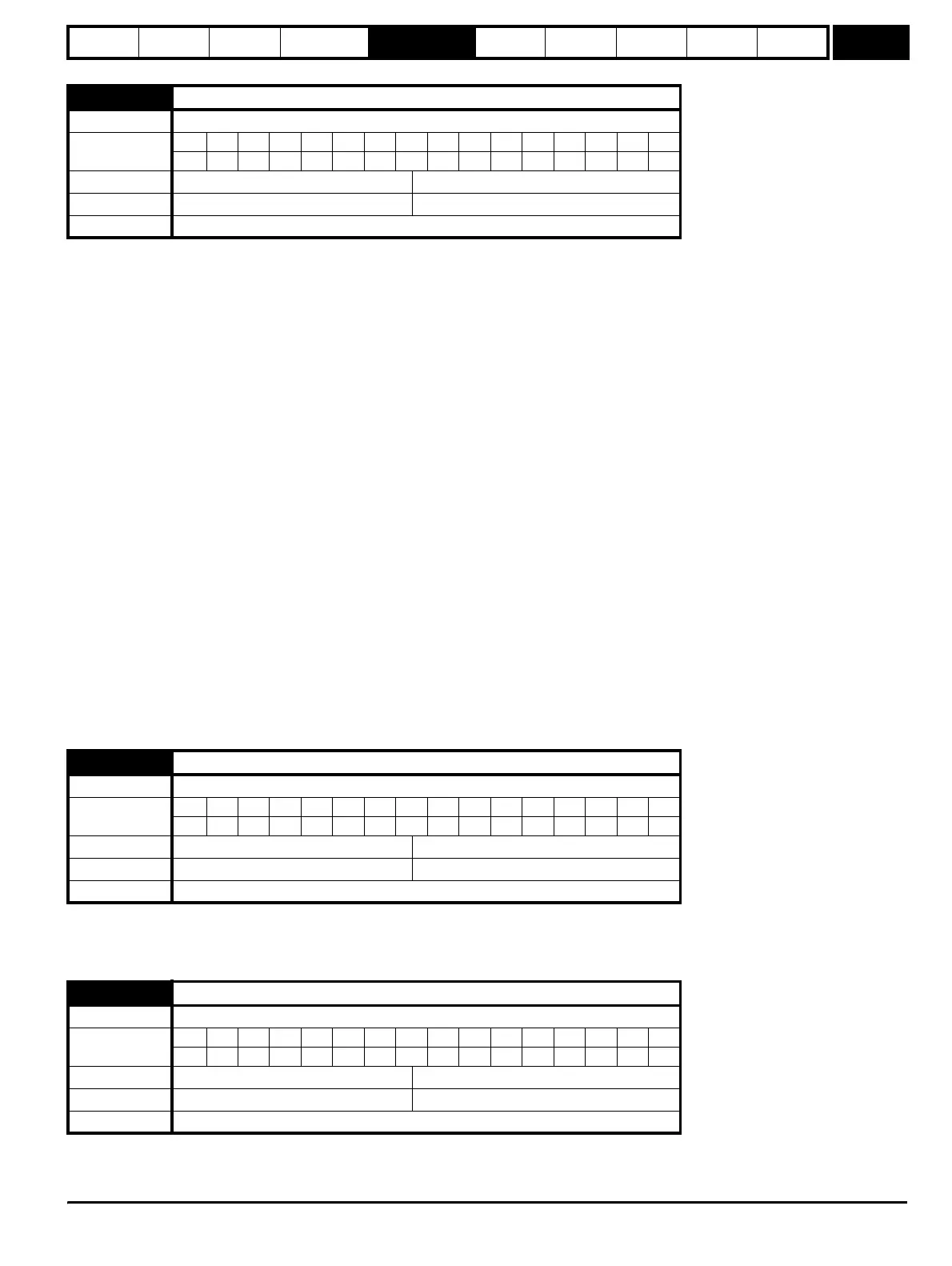
3.17
Speed controller set-up method
Drive modes Closed-loop vector, Servo
Coding
Bit SP FI DE Txt VM DP ND RA NC NV PT US RW BU PS
111
Range Closed-loop vector, Servo 0 to 3
Default Closed-loop vector, Servo 0
Update rate Background (1s) read
3.18
Motor and load inertia
Drive modes Closed-loop vector, Servo
Coding
Bit SP FI DE Txt VM DP ND RA NC NV PT US RW BU PS
5 111
Range Closed-loop vector, Servo
0.00010 to 90.00000 kg m
2
Default Closed-loop vector, Servo 0.00000
Update rate Background (1s) read
3.19
Compliance angle
Drive modes Closed-loop vector, Servo
Coding
Bit SP FI DE Txt VM DP ND RA NC NV PT US RW BU PS
1 111
Range Closed-loop vector, Servo 0.0 to 359.9 °
Default Closed-loop vector, Servo 4.0
Update rate Background (1s) read
http://nicontrols.com