Parameter
structure
Keypad and
display
Parameter
x.00
Parameter
description format
Advanced parameter
descriptions
Macros
Serial comms
protocol
Electronic
nameplate
Performance
Feature look-
up table
Unidrive SP Advanced User Guide 365
Issue Number: 7 www.controltechniques.com
message but forwards the message for processing by the SM-
Applications in slot (port) Y.
SM-Applications notices that the CMP Destination Sub-Node
Address field is 0 and so processes the message and returns a
response.
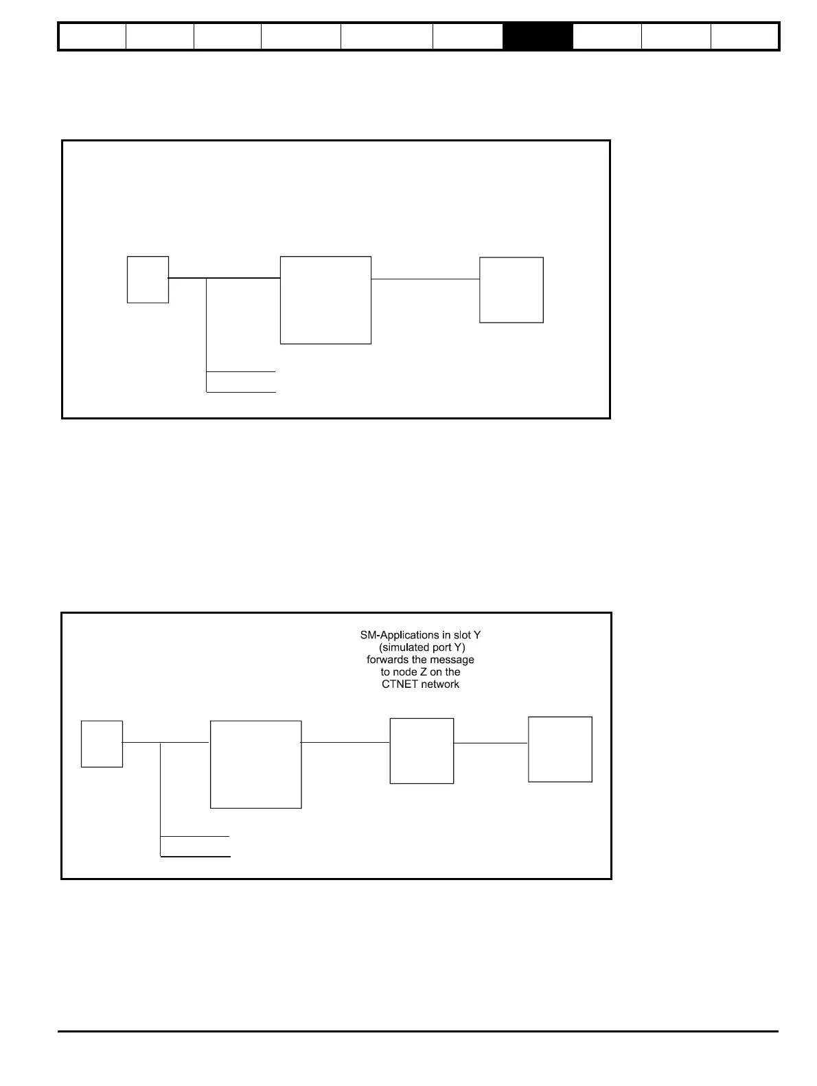
2. Routing of a CT Modbus RTU by Unidrive SP to a SM-Applications
in one of the Unidrive SP options slots and then re-routing by the
SM-Applications onto a CTNet network.
In this example, a PC wishes to communicate with node Z on a
CTNET network connected to a SM-Applications option located in
option slot Y (where Y = 1, 2 or 3) in a Unidrive SP with node
address X on an RS485 network.
The PC sets the Slave Node Address to X, the CMP Destination Port
to Y and the CMP Destination Sub-Node Address field to Z in the CT
Modbus RTU message and transmits the message over a RS485
network connecting the PC and Unidrive SP.
The Unidrive SP receives the message and notices that the CMP
Destination Port has the value Y - Unidrive SP does not process the
message but forwards the message for processing by the SM-
Applications in slot (port) Y.
SM-Applications notices that the CMP Destination Sub-Node
Address field has the value Z and so transmits the CMP portion of
the message over its CTNET connection to node Z.
Node Z receives and processes the message and returns a CMP
response to the SM-Applications. SM-Applications constructs a
suitable CT Modbus RTU response using the CMP response and
sends the reconstructed RTU message back to the PC via Unidrive
SP.
7.2.8 Communications timeouts
When a CT Modbus RTU master sends a message to a slave, the
master should use a timeout to detect a missing response from a slave.
Ideally, a variable timeout will be used based on the number of hops a
CT Modbus RTU message makes between the master and its eventual
destination. For example, in the Unidrive SP/ SM-Applications re-routing
scenarios shown in the previous section, when a PC sends a message
to SM-Applications one hop is performed (through Unidrive SP) to reach
the SM-Applications; when a PC sends a message via through Unidrive
SP and then SM-Applications onto CTNet, two hops are performed.
In practice a master may not be able to handle variable timeouts in such
a fashion. If this is the case a single timeout should be used which is
large enough to cater for the longest route to a destination. The
recommended timeouts for use with a specific product are given in the
specific product user guides.
PC
Unidrive SP
has node
address X on
the RS485
network
SM-Applications
in slot Y
on the
drive
RS485
network
PC sets Slave Node
Address to X, CMP
Destination Port to Y,
CMP Destination Sub-
Node Address to 0
Dual-port
RAM
connection
Unidrive SP receives message over
RS485. Since the CMP
Destination Port has the value Y,
Unidrive SP makes the message
available to slot (port) Y for
processing
in slot Y (simulated port Y
processes message.
More
Unidrive SPs
n
tw
rk
SM-Applications
Figure 7-1 Example message routing from a PC through Unidrive SP to a SM-Applications in a Unidrive SP option slot
PC
Unidrive SP
has node
address X on
the RS485
network
SM-Applications
in slot Y
on the
DB9
RS485
network
Dual-port
RAM
connection
Unidrive SP receives message over
RS485. Since the CMP Destination
Port has the value Y, Unidrive SP
makes the message available to
slot (port) Y for processing.
Node Z
on
CTNet
CTNET
connection
Node Z process
the message
More
Unidrive SPs
network
Figure 7-2 Example message routing from a PC through Unidrive SP and SM-Applications to a CTNet node
http://nicontrols.com