Parameter
structure
Keypad and
display
Parameter
x.00
Parameter
description format
Advanced parameter
descriptions
Macros
Serial comms
protocol
Electronic
nameplate
Performance
Feature look-
up table
Menu 5
Unidrive SP Advanced User Guide 115
Issue Number: 7 www.controltechniques.com
The voltage boost is used in fixed boost mode and square law mode for Open-loop mode, and during the rotating auto-tune test in Closed-loop vector
mode.
The motor rated full load rpm parameter (Pr 5.08) in conjunction with the motor rated frequency parameter (Pr 5.06) defines the full load slip of the
motor. The slip is used in the motor model for closed-loop vector control. The full load slip of the motor varies with rotor resistance which can vary
significantly with motor temperature. When this parameter is set to 1 or 2 the drive can automatically sense if the value of slip defined by Pr 5.06 and
Pr 5.08 has been set incorrectly or has varied with motor temperature. If the value is incorrect Pr 5.08 is automatically adjusted. Pr 5.08 is not saved
at power-down, and so when the drive is powered-down and up again it will return to the last value saved by the user. If the new value is required at
the next power-up it must be saved by the user. Automatic optimisation is only enabled when the frequency is above rated frequency/8, and when the
load on the motor load rises above
5
/
8
rated load. Optimisation is disabled again if the load falls below half rated load. For best optimisation results the
correct values of stator resistance (Pr 5.17), transient inductance (Pr 5.24), stator inductance (Pr 5.25) and saturation breakpoints (Pr 5.29 and Pr
5.30) should be stored in the relevant parameters. Rated rpm auto-tune is not available if the drive is not using external position/speed feedback.
The gain of the optimiser, and hence the speed with which it converges, can be set at a normal low level when Pr 5.16 is set to 1. If this parameter is
set to 2 the gain is increased by a factor of 16 to give faster convergence.
From software version 1.07.00 onwards the maximum value of this parameter increased from 30 to 65 ohms to allow use of the autotune with very
small motors. rS trips will be seen with small motors with a higher resistance than 30 ohms per phase with earlier software versions.
This parameter defines the required switching frequency. The drive may automatically reduce the actual switching frequency (without changing this
parameter) if the power stage becomes too hot. The switching frequency can reduce from 12kHz to 6kHz to 3kHz, or 16kHz to 8kHz to 4kHz. An
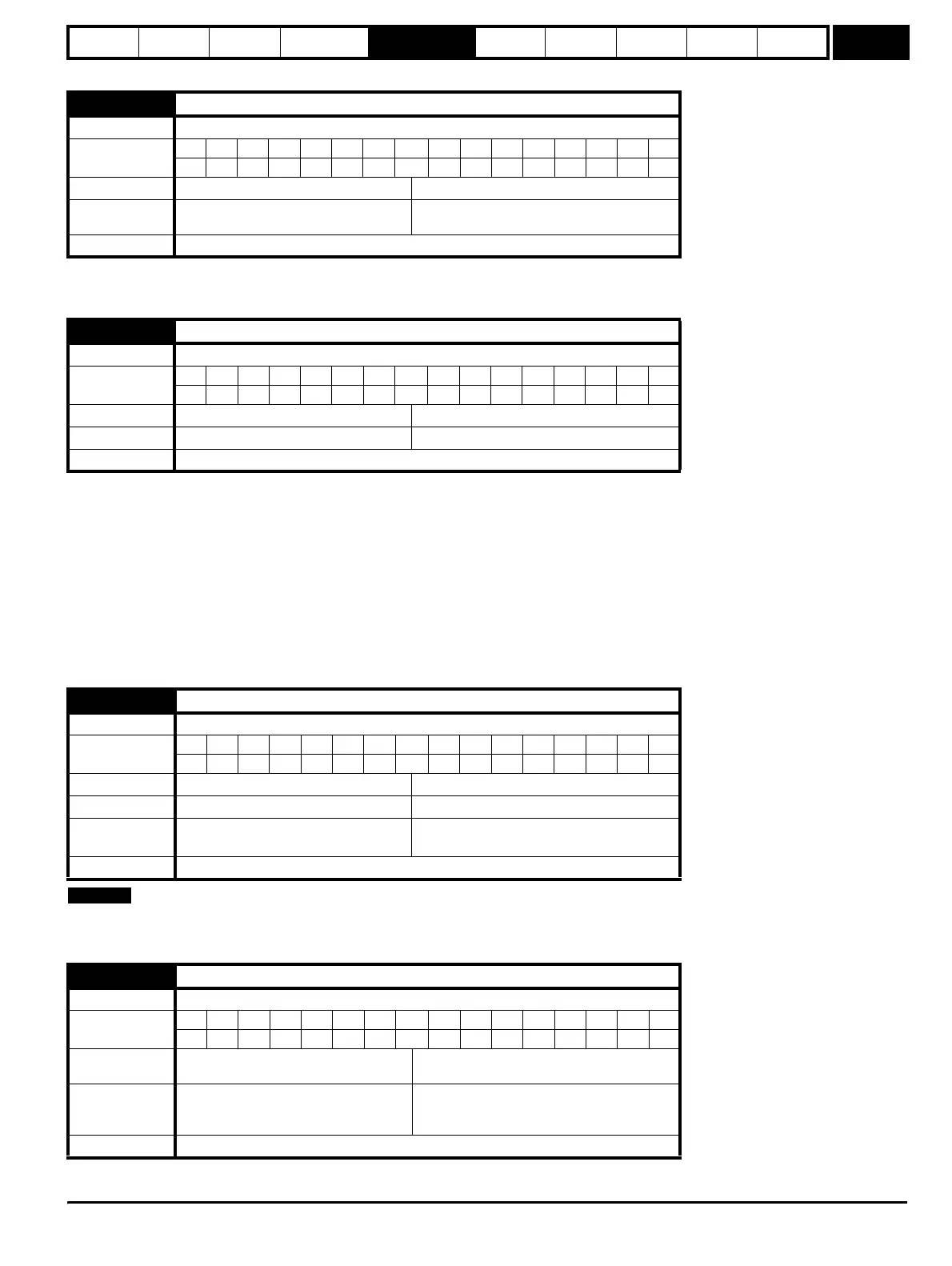
5.15 Low frequency voltage boost
Drive modes Open-loop, Closed-loop vector
Coding
Bit SP FI DE Txt VM DP ND RA NC NV PT US RW BU PS
1111
Range Open-loop, Closed-loop vector 0.0 to 25.0 % of motor rated voltage
Default
Open-loop
Closed-loop vector
3.0
1.0
Update rate Background read
5.16 Rated rpm auto-tune
Drive modes Closed-loop vector
Coding
Bit SP FI DE Txt VM DP ND RA NC NV PT US RW BU PS
11
Range Closed-loop vector 0 to 2
Default Closed-loop vector 0
Update rate Background read
5.17 Stator resistance
Drive modes Open-loop, Closed-loop vector, Servo
Coding
Bit SP FI DE Txt VM DP ND RA NC NV PT US RW BU PS
3 1 111
Range Open-loop, Closed-loop vector, Servo 0.0 to 65.000 Ω
Default Open-loop, Closed-loop vector, Servo 0.0
Second motor
parameter
Open-loop, Closed-loop vector, Servo Pr 21.12
Update rate Background read
5.18 Maximum switching frequency
Drive modes Open-loop, Closed-loop vector, Servo, Regen
Coding
Bit SP FI DE Txt VM DP ND RA NC NV PT US RW BU PS
1 1 111
Range
Open-loop, Closed-loop vector, Servo,
Regen
0 to 5 (3, 4, 6, 8, 12, 16 kHz)
Default
Open-loop, Closed-loop vector, Regen
,
Servo
0 (3 kHz)
2 (6 kHz)
Update rate Background read
NOTE
http://nicontrols.com