Menu 4
Parameter
structure
Keypad and
display
Parameter
x.00
Parameter
description format
Advanced parameter
descriptions
Macros
Serial comms
protocol
Electronic
nameplate
Performance
Feature look-
up table
96 Unidrive SP Advanced User Guide
www.controltechniques.com Issue Number: 7
Closed-loop vector and Servo
The Kp and Ki gains are used in the voltage based current controller. The default values give satisfactory operation with most motors. However it may
be necessary to change the gains to improve the performance. The proportional gain (Pr 4.13) is the most critical value in controlling the
performance. Either the value can be set by auto-tuning (see Pr 5.12 on page 109) or it can be set by the user so that
Pr 4.13 = Kp = (L / T) x (I
fs
/ V
fs
) x (256 / 5)
Where:
T is the sample time of the current controllers. The drive compensates for any change of sample time, and so it should be assumed that the
sample time is equivalent to the lowest sample rate of 167µs.
L is the motor inductance. For a servo motor this is half the phase to phase inductance that is normally specified by the manufacturer. For an
induction motor this is the per phase transient inductance (σLs). This is the inductance value stored in Pr 5.24 after the auto-tune test is carried
out. If σLs cannot be measured it can be calculated (see Pr 5.24 on page 117).
I
fs
is the peak full scale current feedback = Rated drive current x √2 / 0.45. Where rated drive current is given by Pr 11.32.
V
fs
is the maximum DC bus voltage.
Therefore:
Pr 4.13 = Kp= (L / 167µs) x (Rated drive current x
√2 / 0.45 / V
fs
) x (256 / 5)
= K x L x Rated drive current
Where:
K =
√2 / (0.45 x V
fs
x 167µs) x (256 / 5)
This set-up will give a step response with minimum overshoot after a step change of current reference. The approximate performance of the current
controllers will be as given below. The proportional gain can be increased by a factor of 1.5 giving a similar increase in bandwidth, however, this gives
a step response with approximately 12.5% overshoot.
The integral gain (Pr 4.14) is less critical and should be set so that
Pr 4.14 = Ki = Kp x 256 x T /
τ
m
Where:
τ
m
is the motor time constant (L / R).
R is the per phase stator resistance of the motor (i.e. half the resistance measured between two phases).
Therefore
Pr 4.14 = Ki = (K x L x Rated drive current) x 256 x 167µs x R / L
= 0.0427 x K x R x Rated drive current
The previous equation gives a conservative value of integral gain. In some applications where it is necessary for the reference frame used by the
drive to dynamically follow the flux very closely (i.e. high speed closed-loop induction motor applications) the integral gain may need to have a
significantly higher value.
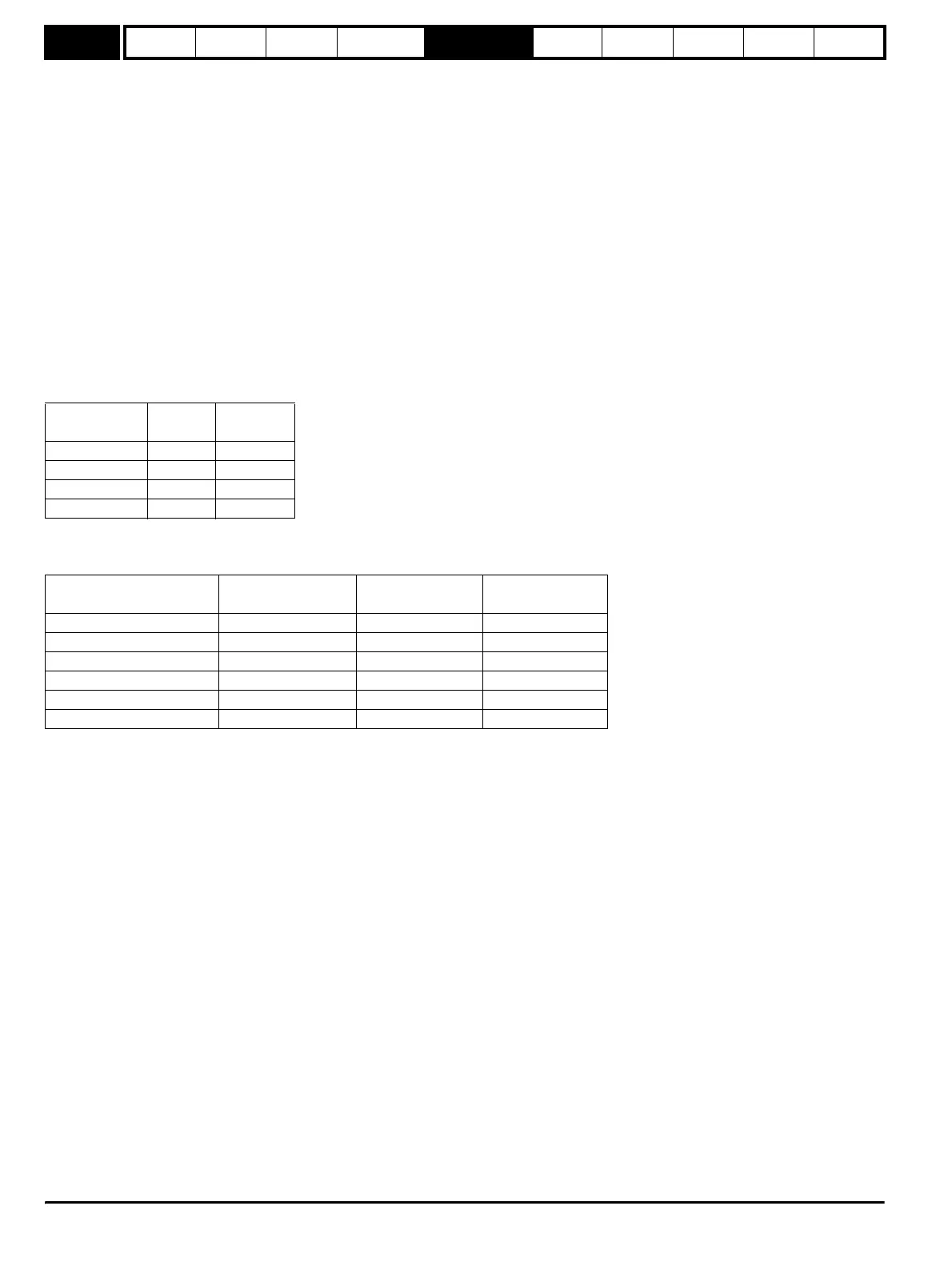
As already stated, the drive compensates for changes of switching frequency to give similar performance as the switching frequency changes. The
following table gives the relationship between the user gain values and the values actually used by the drive for Unidrive and Unidrive SP. Although
other scaling values are included in the current controller these values can be used to make a relative comparison between switching frequencies and
a relative comparison between Unidrive and Unidrive SP. For example: the amount of acoustic noise produced in the motor from encoder speed ripple
is generally related to the product of the speed controller and current controller proportional gains. The values in this table can be used in conjunction
with the speed loop proportional gain to assess the amount of acoustic noise that is likely to be produced from the encoder speed ripple for each
product and with different switching frequencies.
Drive voltage
rating
V
fs
K
200V 415V 2,322
400V 830V 1,161
575V 990V 973
690V 1,190V 951
Switching frequency
(kHz)
Current control
sample time (µs)
Gain bandwidth
(Hz)
Delay
(µs)
3 167 TBA 1,160
4 125 TBA 875
6 83 TBA 581
8 125 TBA 625
12 83 TBA 415
16 125 TBA 625
http://nicontrols.com