Menu 6
Parameter
structure
Keypad and
display
Parameter
x.00
Parameter
description format
Advanced parameter
descriptions
Macros
Serial comms
protocol
Electronic
nameplate
Performance
Feature look-
up table
132 Unidrive SP Advanced User Guide
www.controltechniques.com Issue Number: 7
Bits marked with * have no effect in Regen mode.
Bits 0-7 and bit 9: sequencing control
When the control word is enabled (Pr 6.43 = 1), and the Auto/manual bit (bit7) are both one, bits 0 to 6 and bit 9 of the control word become active.
The equivalent parameters are not modified by these bits, but become inactive when the equivalent bits in the control word are active. When the bits
are active they replace the functions of the equivalent parameters. For example, if Pr 6.43 = 1 and bit 7 of Pr 6.42 = 1 the drive enable is no longer
controlled by Pr 6.15, but by bit 0 of the control word. If either Pr 6.43 = 0, or bit 7 of Pr 6.42 = 0, the drive enable is controlled by Pr 6.15.
Bit 8: Analog/preset reference
When the control word is enabled (Pr 6.43) bit 8 of the control word becomes active. (Bit 7 of the control word has no effect on this function.) The state
of bit 8 is written to Pr 1.42. With default drive settings this selects analogue reference 1 (bit8 = 0) or preset reference 1 (bit8 = 1). If any other drive
parameters are routed to Pr 1.42 the value of Pr 1.42 is undefined.
Bit12: Trip drive
When the control word is enabled (Pr 6.43) bit 12 of the control word becomes active. (Bit 7 of the control word has no effect on this function.) When
bit 12 is set to one a CL.bit trip is initiated. The trip cannot be cleared until the bit is set to zero
Bit 13: Reset drive
When the control word is enabled (Pr 6.43) bit 13 of the control word becomes active. (Bit 7 of the control word has no effect on this function.) When
bit 13 is changed from 0 to 1 the drive is reset. This bit does not modify the equivalent parameter (Pr 10.33).
Bit 14: Keypad watchdog
When the control word is enabled (Pr 6.43) bit 14 of the control word becomes active. (Bit 7 of the control word has no effect on this function.) A
watchdog is provided for an external keypad or other device where a break in the communication link must be detected. The watchdog system can be
enabled and/or serviced if bit 14 of the control word is changed from zero to one with the control word enabled. Once the watchdog is enabled it must
be serviced at least once every second or an “SCL” trip occurs. The watchdog is disabled when an “SCL” trip occurs, and so it must be re-enabled
when the trip is reset.
The drive can operate from either a high voltage supply or a low voltage supply, usually from a battery. Different methods are used to connect the low
voltage battery supply depending on the frame size of the drive. This parameter, which indicates which supply is active, is set up to the correct value
just as the UU trip is reset. A low voltage battery supply should not be used without first consulting the appropriate documentation on the power and
control connections required for this mode.
0: Normal high voltage supply
The drive is operating in normal high voltage supply mode.
UNISP1xxx, UNISP2xxx, UNISP3xxx:
The drive is using the main power terminals to derive its control supplies. The drive will operate normally. Parameters that are saved at power-down
are saved when the supply is removed and a UU trip occurs.
UNISP4xxx, UNISP5xxx, UNISP6xxx, UNISP7xxx:
The drive is using the main power terminals to derive its control supplies and the battery mode enable power supply input has no supply connected.
The drive will operate normally. Parameters that are saved at power-down are saved when the supply is removed and a UU trip occurs.
1: Low voltage battery supply
The drive is operating in low voltage battery supply mode.
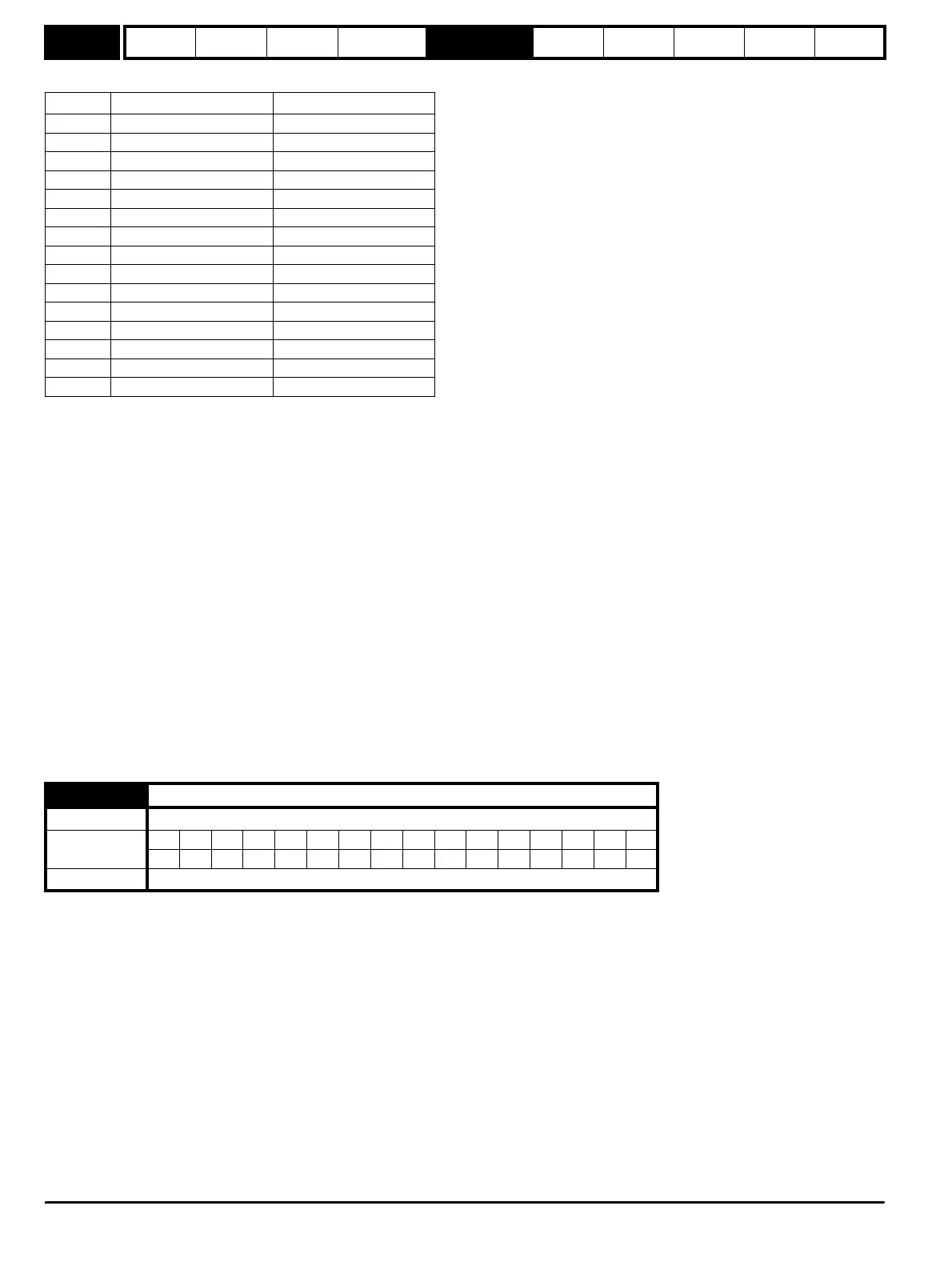
Bit Function Equivalent parameter
0 Drive enable Pr 6.15
1* Run forward Pr 6.30
2* Jog Pr 6.31
3* Run reverse Pr 6.32
4* Forward/reverse Pr 6.33
5* Run Pr 6.34
6* Not stop Pr 6.39
7 Auto/manual
8* Analogue/Preset reference Pr 1.42
9* Jog reverse Pr 6.37
10 Reserved
11 Reserved
12 Trip drive
13 Reset drive Pr 10.33
14 Keypad watchdog
6.44 Active supply
Drive modes Open-loop, Closed-loop vector, Servo, Regen
Coding
Bit SP FI DETEVMDPNDRANCNVPTUSRWBUPS
1 111
Update rate Background write
http://nicontrols.com