Parameter
structure
Keypad and
display
Parameter
x.00
Parameter
description format
Advanced parameter
descriptions
Macros
Serial comms
protocol
Electronic
nameplate
Performance
Feature look-
up table
352 Unidrive SP Advanced User Guide
www.controltechniques.com Issue Number: 7
6.8 Macro 7 - Brake control
Table 6-14 Macro 7 menu 0 programmable parameters
Where a safety hazard may exist the drive alone must not be permitted to release the brake. An independent safety interlock must be
provided to ensure safe operation in the event of drive failure or incorrect operation.
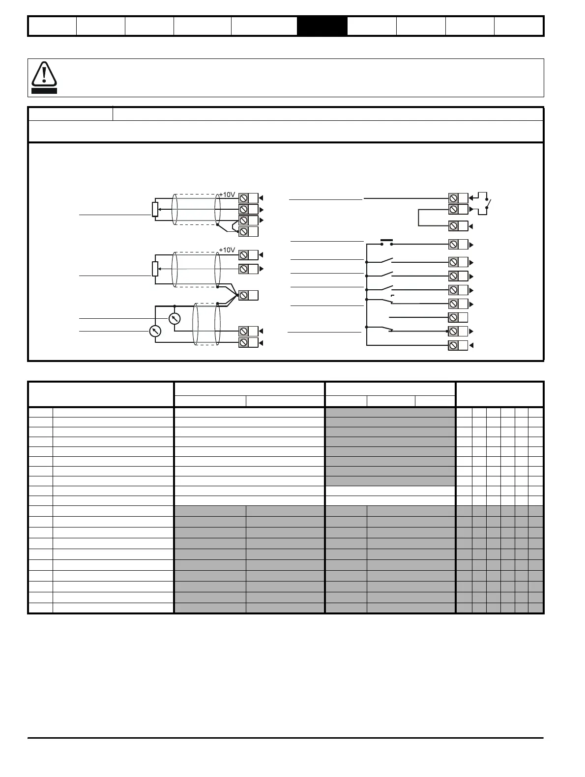
Macro 7 Brake control
The brake control macro configures the drive to apply or release a mechanical brake on a motor in a crane or hoist application. The drive issues a
brake release signal via a digital output when the relevant conditions are met.
WARNING
0V common
Analog
frequency/speed
reference 1
0 ~ 10V
SPEED
TORQUE
0V common
BRAKE RELEASE
RESET
CL> JOG
RUN FORWARD
ANALOG INPUT 2
ANALOG INPUT 1
RUN REVERSE
ANALOG INPUT 1 /
INPUT 2
Signal
connector
Analog
frequency/speed
reference 2
0 ~ 10V
24
25
29
26
27
28
41
42
4
5
6
3
7
11
9
10
4
0V common
30
31
+24V
22
DRIVE ENABLE
Analog I/O Digital I/O
Parameter
Range(
Ú) Default(Ö)
Type
OL CL OL VT SV
0.11 Pre-ramp reference {1.03} ±SPEED_FREQ_MAX Hz/rpm
RO Bi NC PT
0.12 Post ramp reference {2.01} ±SPEED_FREQ_MAX Hz/rpm
RO Bi PT
0.13 Active current {4.02} ±DRIVE_CURRENT_MAX A
RO Bi FI NC PT
0.14 Current magnitude {4.01} 0 to DRIVE_CURRENT_MAX A
RO Uni FI NC PT
0.15 Threshold detector 1 output {12.01} OFF (0) or On (1)
RO Bit NC PT
0.16 Drive healthy {10.01} OFF (0) or On (1)
RO Bit NC PT
0.17 Zero speed {10.03} OFF (0) or On (1)
RO Bit NC PT
0.18 Logic function 1 output {9.01} OFF (0) or On (1)
RO Bit NC PT
0.19 Threshold detector 1 level {12.04} 0.00 to 100.00 % 0.00 RW Uni US
0.20 Logic function 2 delay {9.19}±25.0 s 0.0RWBiUS
0.21 Not used
0.22 Not used
0.23 Not used
0.24 Not used
0.25 Not used
0.26 Not used
0.27 Not used
0.28 Not used
0.29 Not used
0.30 Not used
http://nicontrols.com