Menu 5
Parameter
structure
Keypad and
display
Parameter
x.00
Parameter
description format
Advanced parameter
descriptions
Macros
Serial comms
protocol
Electronic
nameplate
Performance
Feature look-
up table
118 Unidrive SP Advanced User Guide
www.controltechniques.com Issue Number: 7
Based on the parameters normally used for the motor equivalent circuit for transient analysis, i.e. L
s
= L
1
+ L
m
, L
r
= L
2
+ L
m
, the transient inductance
is given by
σL
s
= L
s
- (L
m
2
/ L
r
)
The transient inductance is used as an intermediate variable to calculate the power factor in open-loop mode. It is used in the vector algorithm, for
cross-coupling compensation and to set the current controller gains in closed-loop vector mode.
Servo
The transient inductance is the phase inductance for a servo motor. This is half the inductance measured from phase to phase. This value is used for
cross-coupling compensation and to set the current controller gains.
This parameter holds the stator inductance of the motor with rated flux. If the motor flux is reduced the value of stator inductance used by the vector
control algorithm is modified using the motor saturation breakpoints (Pr 5.29 and Pr 5.30). Stator inductance (L
s
) = L
1
+ L
m
from the steady state
equivalent circuit. It should be noted that if this parameter is changed from a non-zero value to zero the power factor (Pr 5.10) is automatically set to
0.850. The same applies to the motor map 2 stator inductance (Pr 21.24) and motor map 2 power factor (Pr 21.10).
When this bit is set the drive provides a cross-coupling feed forward voltage as produced by the transient inductance and a frequency based voltage
feed forward term. These voltages improve the transient performance of the current controllers
The level of slip compensation is set by the rated frequency and rated speed parameters. Slip compensation is only enabled when this parameter is
set to 1 and Pr 5.08 is set to a value other than zero or synchronous speed.
5.25
Stator inductance (L
s
)
Drive modes Closed-loop vector
Coding
Bit SP FI DE Txt VM DP ND RA NC NV PT US RW BU PS
21 111
Range Closed-loop vector 0.00 to 5000.00 mH
Default Closed-loop vector 0.00
Second motor
parameter
Closed-loop vector Pr 21.24
Update rate Background read
5.26 High dynamic performance enable
Drive modes Closed-loop vector, Servo
Coding
Bit SP FI DE Txt VM DP ND RA NC NV PT US RW BU PS
111
Default Closed-loop vector, Servo 0
Update rate Background read
5.27 Enable slip compensation
Drive modes Open-loop
Coding
Bit SP FI DE Txt VM DP ND RA NC NV PT US RW BU PS
1111
Default Open-loop 1
Update rate Background read
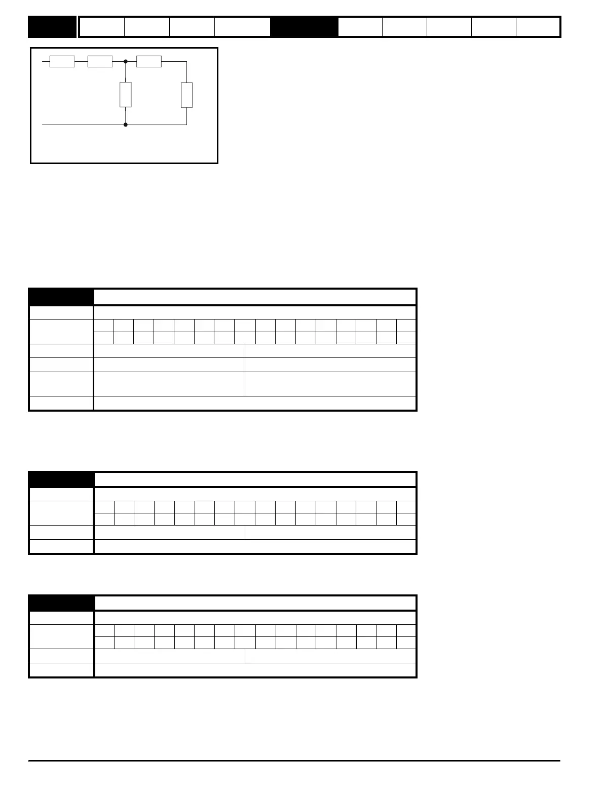
R
1
jwL
1
jwL
2
R
2
/sjwL
m
Steady state per phase equivalent circuit
of an induction motor
http://nicontrols.com