Menus 15 to 17
SM-Uni Enc Pl
Parameter
structure
Keypad and
display
Parameter
x.00
Parameter
description format
Advanced parameter
descriptions
Macros
Serial comms
protocol
Electronic
nameplate
Performance
Feature look-
up table
234 Unidrive SP Advanced User Guide
www.controltechniques.com Issue Number: 7
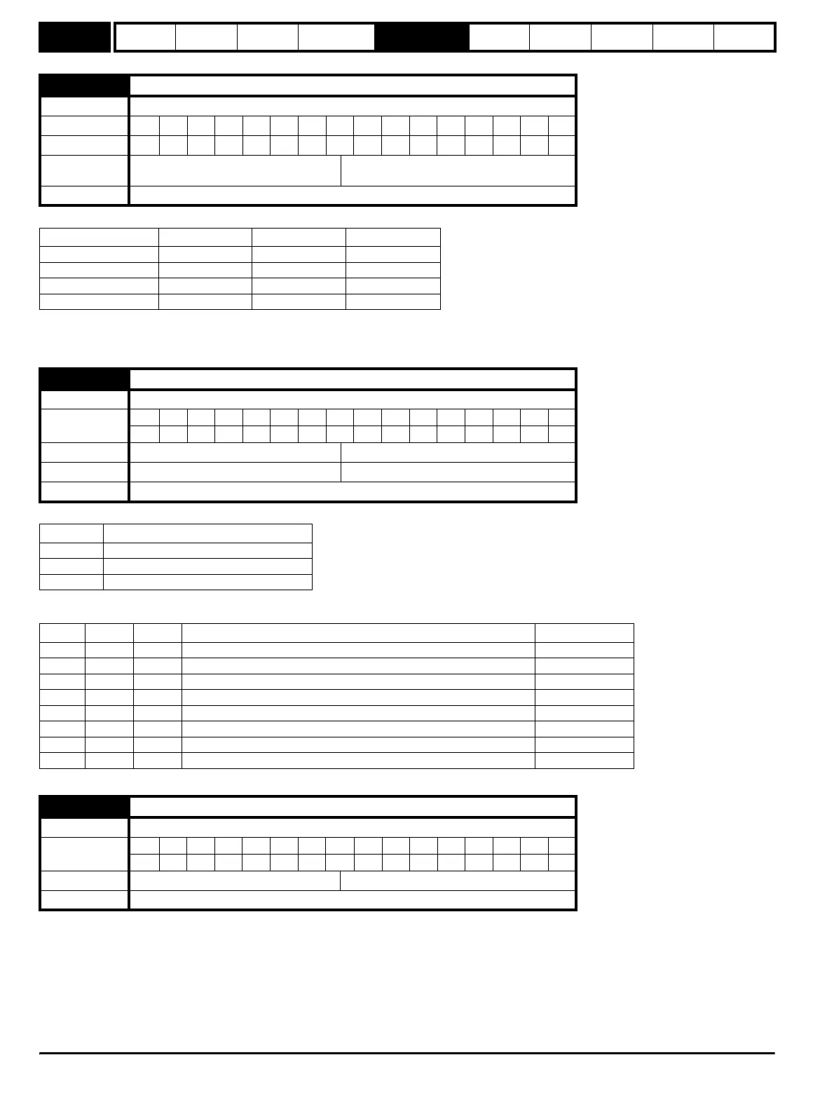
The terminations may be enabled/disabled by this parameter as follows:
A-A\ and B-B\ terminations cannot be disabled when encoders with SinCos waveforms are selected.
Z-Z\ terminations cannot be disabled except when Ab, Fd, Fr, Ab.Servo, Fd.Servo, Fr.Servo encoders are selected.
Trips can be enabled/disabled using Pr x.17 as follows:
The binary sum defines the level of error detection as below:
SC.Hiper, SC.EnDat, EnDat
When a SC.Hiper, SC.EnDat or EnDat encoder is being used, the Solutions Module will interrogate the encoder on power-up. If Pr x.18 is set and the
encoder type is recognised based on the information provided by the encoder, the Solutions Module will set the encoder turns (Pr x.09), the
equivalent lines per revolution (Pr x.10) and the encoder comms resolution (Pr x.11) for the encoder. If the encoder is recognised these parameters
will all become read only. If the encoder is not recognised, the Solutions Module initiates an SLx.Er trip (Pr x.50 = 7) to prompt the user to enter the
information. The Solutions Module should be able to auto-configure with any EnDat encoder where the number of turns and lines per revolution are a
power of 2, and the following HIPERFACE encoders: SCS 60/70, SCM 60/70, SRS 50/60, SRM 50/60, SHS 170, LINCODER, SCS-KIT 101, SKS36,
SKM36.
x.16 Encoder termination
Drive modes Open-loop, Closed-loop vector, Servo, Regen
Coding Bit SP FI DE Txt VM DP ND RA NC NV PT US RW BU PS
111
Default
Open-loop, Closed-loop vector, Servo,
Regen
1
Update rate Background read
Encoder input Pr x.16=0 Pr x.16=1 Pr x.16=2
A-A\ Disabled Enabled Enabled
B-B\ Disabled Enabled Enabled
Z-Z\ Disabled Disabled Enabled
U-U\ V-V\ W-W\ Enabled Enabled Enabled
x.17 Error detection level
Drive modes Open-loop, Closed-loop vector, Servo
Coding
Bit SP FI DE Txt VM DP ND RA NC NV PT US RW BU PS
111
Range Open-loop, Closed-loop vector, Servo 0 to 7
Default Open-loop, Closed-loop vector, Servo 0
Update rate Background read
Bit Function
0 Wire break detect
1 Phase error detect
2 SSI power supply bit monitor
Bit 2 Bit 1 Bit 0 Error detection level Value in Pr x.17
0 0 0 Error detection disabled 0
0 0 1 Wire break detect 1
0 1 0 Phase error detect 2
0 1 1 Wire break + phase error detect 3
1 0 0 SSI power supply bit monitor 4
1 0 1 Wire break + SSI power supply bit monitor 5
1 1 0 Phase error detect + SSI power supply bit monitor 6
1 1 1 Wire break detect + phase error detect + SSI power supply bit monitor 7
x.18 Auto configuration enable / SSI binary format select
Drive modes Open-loop, Closed-loop vector, Servo
Coding
Bit SP FI DE Txt VM DP ND RA NC NV PT US RW BU PS
1111
Default Open-loop. Closed-loop vector, Servo 0
Update rate Background read
http://nicontrols.com