Parameter
structure
Keypad and
display
Parameter
x.00
Parameter
description format
Advanced parameter
descriptions
Macros
Serial comms
protocol
Electronic
nameplate
Performance
Feature look-
up table
Unidrive SP Advanced User Guide 363
Issue Number: 7 www.controltechniques.com
To correctly map the parameters at the application layer, the slave
device increments the received register address. The consequence of
this behaviour is that #0.0 cannot be accessed.
Data types
The MODBUS protocol specification defines registers as 16bit signed
integers. All CT devices support this data size.
Refer to the section 7.2.9 Extended data types on page 366 for detail on
accessing 32bit register data.
7.2.4 Data consistency
All CT devices support a minimum data consistency of one parameter
(16bit or 32bit data). Some devices support consistency for a complete
multiple register transaction.
7.2.5 Data encoding
MODBUS RTU uses a 'big-endian' representation for addresses and
data items (except the CRC, which is 'little-endian'). This means that
when a numerical quantity larger than a single byte is transmitted, the
MOST significant byte is sent first. So for example
16 - bits 0x1234 would be 0x12 0x34
32 - bits 0x12345678L would be 0x12 0x34 0x56 0x78
7.2.6 Function codes
The function code determines the context and format of the message
data. Bit 7 of the function code is used in the slave response to indicate
an exception.
The following function codes are supported:
FC03 Read multiple
Read a contiguous array of registers. The slave imposes an upper limit
on the number of registers, which can be read. If this is exceeded the
slave will issue an exception code 2.
Table 7-1 Master request
Table 7-2 Slave response
FC6 Write single register
Writes a value to a single 16bit register. The normal response is an echo
of the request, returned after the register contents have been written.
The register address can correspond to a 32bit parameter but only 16
bits of data can be sent.
Table 7-3 Master request
Table 7-4 Slave response
FC16 Write multiple
Writes a contiguous array of registers. The slave imposes an upper limit
on the number of registers which can be written. If this is exceeded the
slave will discard the request and the master will time out.
Table 7-5 Master request
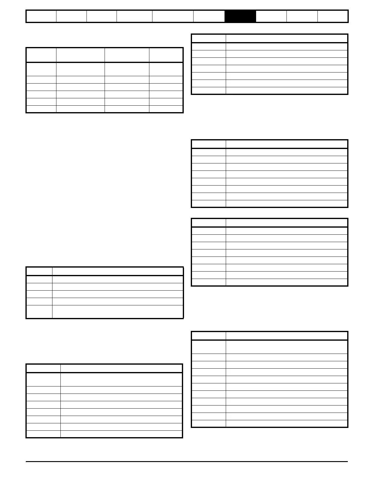
CT
parameter
MODBUS PLC
register
Register address
(protocol level)
Comments
#X.Y 40000 + X x 100 + Y X x 100 + Y - 1
#0.0 cannot
be accessed
Examples:
#1.2 40102 101
#1.0 40100 99
#0.1 40001 0
#70.0 47000 6999
Code Description
3 Read multiple 16bit registers
6 Write single register
16 Write multiple 16bit registers
23 Read and write multiple 16bit registers
64
CMP encapsulated protocol
Non-standard function code
Byte Description
0
Slave destination node address 1 through 247, 0 is
global
1 Function code 0x03
2 Start register address MSB
3 Start register address LSB
4 Number of 16bit registers MSB
5 Number of 16bit registers LSB
6 CRC LSB
7 CRC MSB
Byte Description
0 Slave source node address
1 Function code 0x03
2 Length of register data in read block (in bytes)
3 Register data 0 MSB
4 Register data 0 LSB
3+byte count CRC LSB
4+byte count CRC MSB
Byte Description
0 Slave node address 1 through 247 0 is global
1 Function code 0x6
2 Register address MSB
3 Register address LSB
4 Register data MSB
5 Register data LSB
6 CRC LSB
7 CRC MSB
Byte Description
0 Slave source node address
1 Function code 0x6
2 Register address MSB
3 Register address LSB
4 Register data MSB
5 Register data LSB
6 CRC LSB
7 CRC MSB
Byte Description
0
Slave node address 1 through 247
0 is global
1 Function code 0x10
2 Start register address MSB
3 Start register address LSB
4 Number of 16bit registers MSB
5 Number of 16bit registers LSB
6 Length of register data to write (in bytes)
7 Register data 0 MSB
8 Register data 0 LSB
7+byte count CRC LSB
8+byte count CRC MSB
http://nicontrols.com