Parameter
structure
Keypad and
display
Parameter
x.00
Parameter
description format
Advanced parameter
descriptions
Macros
Serial comms
protocol
Electronic
nameplate
Performance
Feature look-
up table
Menus 15 to 17
SM-Uni Enc Pl
Unidrive SP Advanced User Guide 225
Issue Number: 7 www.controltechniques.com
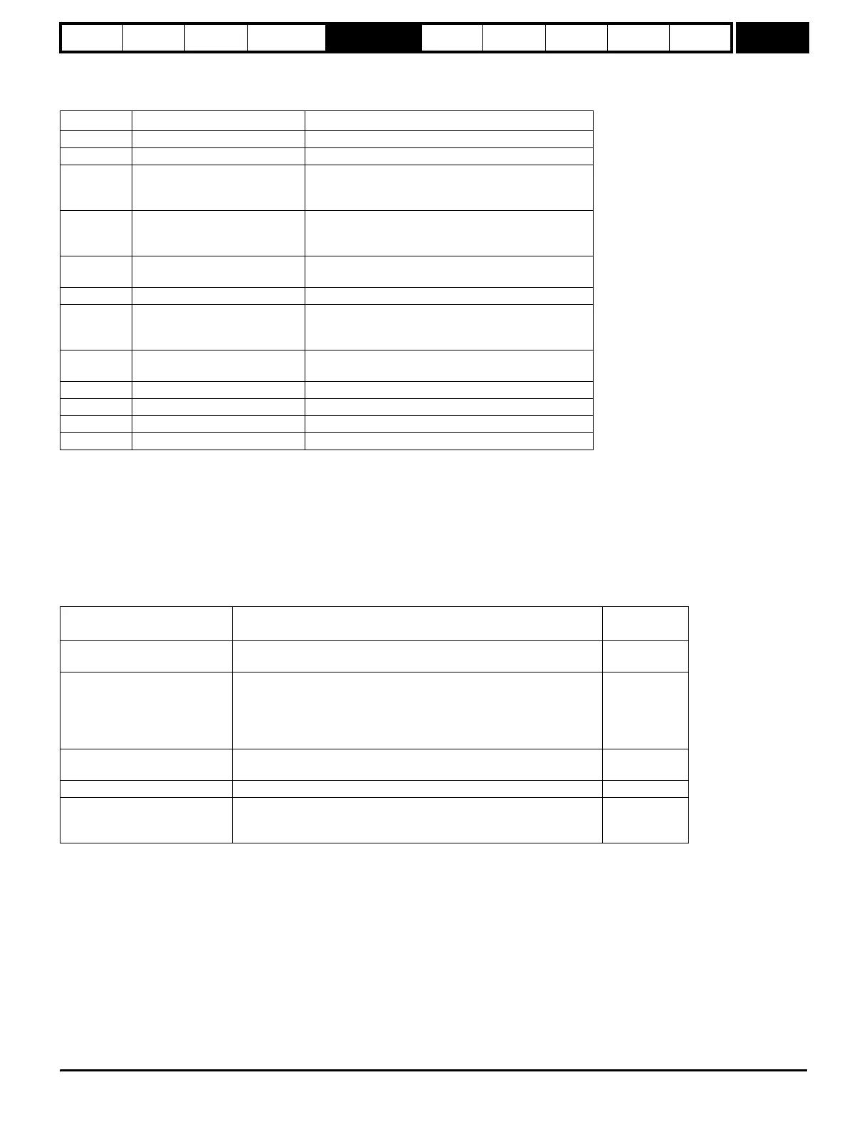
5.16.1 SM-Universal Encoder Plus
Solutions Module error status values
The Solutions Module checks for various errors as shown below.
* Phase errors are detected when the error is greater than 10
o
electrical over ten consecutive one second samples.
+ These trips can be enabled/disabled by Pr x.17.
# If the terminations are not enabled on the A, B or Z inputs the wire break system will not operate. (Note that as default the Z input terminations are
disabled to disable wire break detection on this input.)
Encoder initialisation will occur when trips 1 to 8 are reset. This causes an encoder with comms to be re-initialised and auto-configuration to be
performed if selected. Ab.Servo, Fd.Servo and Fr.Servo encoders will use the UVW commutations signals for the first 120° electrical when the motor
is restarted.
It is important that a break in the connections between the drive and the position feedback device can be detected. This feature is provided either
directly or indirectly as listed below.
Error code Encoders Reason for error
0 All No fault detected
1 All Power supply short circuit
2
Ab, Fd, Fr, Ab.Servo, Fd.Servo,
Fr.Servo, SC, SC.Hiper,
SC.EnDat, SC.SSI
+#Wire-break detect
3
Ab.Servo, Fd.Servo, Fr.Servo
SC.Hiper, SC.EnDat, SC.SSI
+UVW phase angle incorrect while running, i.e.
incremental pulses not counted correctly.
+*Sine/cosine phase error.
4
SC.Hiper, SC.EnDat, EnDat
SSI, SC.SSI
+Comms failure (time-out)
5 SC.Hiper, SC.EnDat, EnDat Checksum or CRC error
6
SC.Hiper, SC.EnDat, EnDat
SSI, SC.SSI
The encoder has indicated an error.
Data was not at one before position was transmitted.
Power supply bit error.
7
SC, SC.Hiper, SC.EnDat,
EnDat, SSI, SC.SSI
Initialisation failed
8 SC.Hiper, SC.EnDat, EnDat Auto configuration failed
9 All Thermistor trip
10 All Thermistor short circuit
74 All The Solutions Module has overheated
Device Detection method
Error
produced
Ab, Fd, Fr, Ab.Servo, Fd.Servo,
Fr.Servo
Hardware detectors on the A(F), B(D,R) and Z signal detect a wire
break.
2
SC, SC.HiPEr,
SC.EnData
The differential levels of the sine and cosine waveforms are available to
the drive. The drive detects wire break if Sine
2
+Cosine
2
is less than the
value produced by two valid waveforms with a differential peak to peak
magnitude of 0.25V (1/4 of the nominal level). This detects wire break in
the sine and cosine connections.
2
SC.HiPEr, SC.EnDat, EnDat
Wire break in the comms link is detected by a CRC or time-out error.
Data line (Z) checked. Comms transfer time too long.
4, 5
SC.HiPEr, SC.EnDat, EnDat The encoder has failed to initialise. 7
SC.HiPEr, SC.EnDat, EnDat
Auto parameter configuration on power-up has been requested Pr
x.17>1 but the encoder type has not been recognised. The user must
supply Pr x.09 and Pr x.11 and possibly Pr x.10.
8
http://nicontrols.com