Menu 5
Parameter
structure
Keypad and
display
Parameter
x.00
Parameter
description format
Advanced parameter
descriptions
Macros
Serial comms
protocol
Electronic
nameplate
Performance
Feature look-
up table
116 Unidrive SP Advanced User Guide
www.controltechniques.com Issue Number: 7
estimate of the IGBT junction temperature is made based on the heatsink temperature and an instantaneous temperature drop using the drive output
current and switching frequency. The estimated IGBT junction temperature is displayed in Pr 7.34. If the temperature exceeds 135°C the switching
frequency is reduced if this is possible (i.e >4kHz) and this mode is enabled (see Pr 5.35 on page 121). Reducing the switching frequency reduces the
drive losses and the junction temperature displayed in Pr 7.34 also reduces. If the load condition persists the junction temperature may continue to
rise. If the temperature exceeds 145°C and the switching frequency cannot be reduced the drive will initiate an O.ht1 trip. Every 20ms the drive will
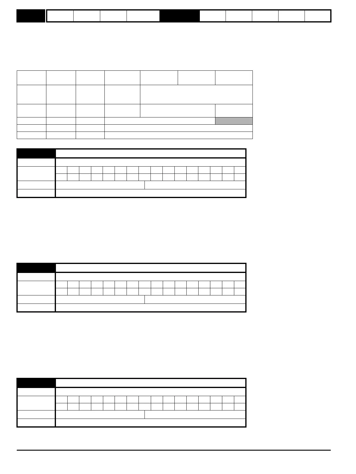
attempt to restore the switching frequency if the higher switching frequency will not take the IGBT temperature above 135°C. The following table gives
the sampling rate for different sections of the control system for different switching frequencies.
Normally the drive will use space vector modulation to produce the IGBT control signals. High stability space vector modulation offers three
advantages in an open loop drive, but the acoustic noise produced by the motor may increase slightly
.
• It is possible for instability to occur around motor rated frequency/2 on light load. The drive uses dead-time compensation to reduce this effect,
however, it is still possible that some machines will be unstable. To prevent this, high stability space vector modulation should be enabled by
setting this parameter.
• As the output voltage approaches the maximum available from the drive pulse deletion occurs. This can cause unstable operation with a lightly or
fully loaded machine. High stability space vector modulation will reduce this effect.
• High stability space vector modulation also gives a small reduction in drive heat loss.
Open loop
The maximum modulation level of the drive is normally limited to unity giving an output voltage equivalent to the drive input voltage minus voltage
drops within the drive. If the motor rated voltage is set at the same level as the supply voltage some pulse deletion will occur as the drive output
voltage approaches the rated voltage level. If Pr 5.20 is set to 1 the modulator will allow over modulation, so that as the output frequency increases
beyond the rated frequency the voltage continues to increase above the rated voltage. The modulation depth will increase beyond unity; first
producing trapezoidal and then quasi-square waveforms. This can be used for example to obtain high output frequencies with a low switching
frequency which would not be possible with space vector modulation limited to unity modulation depth. The disadvantage is that the machine current
will be distorted as the modulation depth increases above unity, and will contain a significant amount of low order odd harmonics of the fundamental
output frequency.
A suitable field controller gain is automatically set by the drive from the motor parameters. However it is possible by setting this parameter to a 1 to
reduce this gain by a factor of 2 if instability problems occur above base speed.
3, 6, 12kHz 4, 8, 16kHz Open-loop
Closed-loop
vector
Servo Regen
Level 1
3 = 167µs
6 = 83µs
12 = 83µs
125µs Peak limit Current controllers
Level 2 250µs 250µs
Current limit
and ramps
Speed controller and ramps
Voltage
controller
Level 3 1ms 1ms Voltage controller
Level 4 4ms 4ms Time critical user interface
Background N/A N/A Non-time critical user interface
5.19 High stability space vector modulation
Drive modes Open-loop
Coding
Bit SP FI DE Txt VM DP ND RA NC NV PT US RW BU PS
111
Default Open-loop, 0
Update rate Background read
5.20 Quasi-square enable
Drive modes Open-loop
Coding
Bit SP FI DE Txt VM DP ND RA NC NV PT US RW BU PS
111
Default Open-loop 0
Update rate Background read
5.21 Field gain reduction
Drive modes Closed-loop vector, Servo
Coding
Bit SP FI DE Txt VM DP ND RA NC NV PT US RW BU PS
111
Default Closed-loop vector, Servo 0
Update rate Background read
http://nicontrols.com