Menu 3
All modes
Parameter
structure
Keypad and
display
Parameter
x.00
Parameter
description format
Advanced parameter
descriptions
Macros
Serial comms
protocol
Electronic
nameplate
Performance
Feature look-
up table
62 Unidrive SP Advanced User Guide
www.controltechniques.com Issue Number: 7
An incremental digital encoder may have a marker channel. When this channel becomes active it may be used to reset the encoder position and set
the marker flag (Pr 3.31 = 0), or just to set the marker flag (Pr 3.31 = 1). When the position is reset by the marker, Pr 3.29 and Pr 3.30 are reset to
zero. The marker flag is set each time the marker input becomes active, but it is not reset by the drive, and so this flag must be cleared by the user.
The marker function only operates when Ab, Fd, Fr, Ab.Servo, Fd.Servo, Fr.Servo type encoders are selected with Pr 3.38.
This parameter has a different function depending on the type of encoder selected with Pr 3.38 and Pr 3.39.
Ab, Fd, Fr, Ab.Servo, Fd.Servo, Fr.Servo, SC
It is sometimes desirable to mask off the most significant bits of the revolution counter with these types of encoders. This does not have to be done for
the drive to function correctly. If Pr 3.33 is zero the revolution counter (Pr 3.28) is held at zero. If Pr 3.33 has any other value it defines the maximum
number of the revolution counter before it is reset to zero. For example, if Pr 3.33 = 5, then Pr 3.28 counts up to 31 before being reset. If Pr 3.33 is
greater than 16, the number of turns bits is 16 and the Pr 3.28 counts up to 65535 before being reset.
SC.Hiper, SC.EnDat, SC.SSI and 03.39 = 1 or 2 (Rotary encoder)
Pr 3.33 must contain the number of bits in the comms message used to give the multi-turn information. For a single turn comms encoder, Pr 3.33
must be set to zero. As well as setting the number of comms turns bits this parameter also sets up a mask on the turns displayed in Pr 3.28 as
described above. With SC.Hiper or SC.EnDat encoders it is possible for this parameter to be obtained automatically from the encoder (see Pr 3.41).
If Pr 3.33 is greater than 16 the number of turns bits is 16.
SC.Hiper, SC.EnDat, SC.SSI and 03.39 = 0 (Linear encoder)
When a linear encoder is selected no mask is placed on the turns information displayed in Pr 3.28, and so this parameter always displays the turns
information as a full 16 bit value with a maximum of 65535. Linear SINCOS encoders with comms are normally specified with a length for each sine
wave period and the length for the least significant bit of the position in the comms message. Pr 3.33 should be set up with the ratio between these
two lengths so that the drive can determine the drive encoder position during initialisation. The Linear encoder comms to sine wave ratio is defined as
follows:
With SC.Hiper or SC.EnDat encoders it is possible for this parameter to be obtained automatically from the encoder (see Pr 3.41).
EnDat, SSI
Pr 3.33 must contain the number of bits in the comms message used to give the multi-turn information. For a single turn comms encoder, Pr 3.33
must be set to zero. As well as setting the number of comms turns bits this parameter also sets up a mask on the turns displayed in Pr 3.28 as
described above. It is possible for this parameter to be obtained automatically from the encoder (see Pr 3.41). If Pr 3.33 is greater than 16 the number
of turns bit is 16.
Support for non power of 2 encoders was added as follows :
From software version 1.06.00 onwards - SC and SC.Endat type encoders
From software version 01.06.01 onwards - SC.Hiper, SC.SSI, Ab.servo, Fr.servo and Fd.servo type encoders.
For example - a Unidrive SP with software prior to 1.06.01 in servo mode does not store the phase offset if used with a 2000PPR quadrature encoder
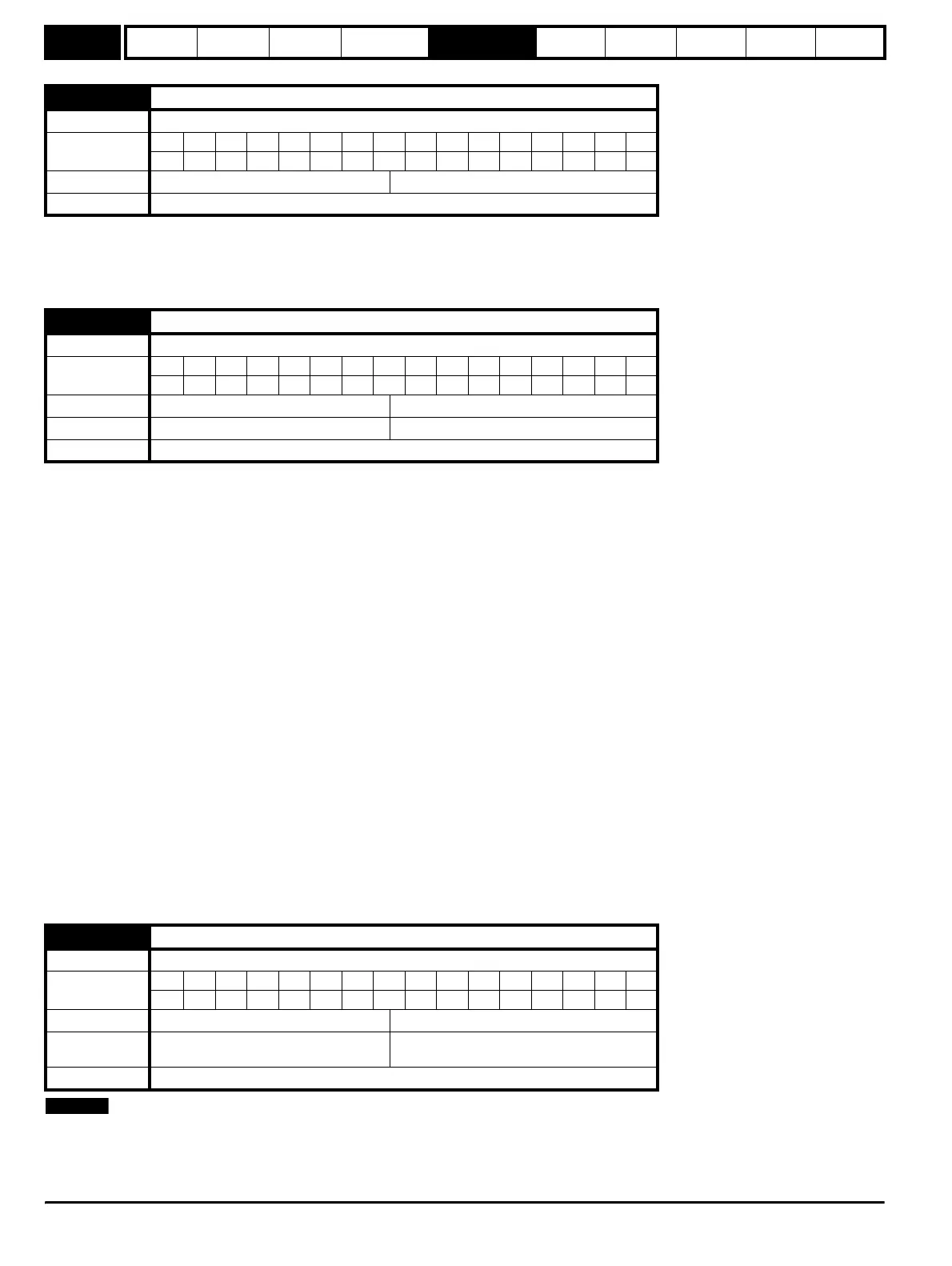
3.32
Drive encoder marker flag
Drive modes Open-loop, Closed-loop vector, Servo
Coding
Bit SP FI DE Txt VM DP ND RA NC NV PT US RW BU PS
111
Default Open-loop, Closed-loop vector, Servo 0
Update rate 250µs write
3.33
Drive encoder turns bits / Linear encoder comms to sine wave ratio
Drive modes Open-loop, Closed-loop vector, Servo
Coding
Bit SP FI DE Txt VM DP ND RA NC NV PT US RW BU PS
111
Range Open-loop, Closed-loop vector, Servo 0 to 255
Default Open-loop, Closed-loop vector, Servo 16
Update rate Background read (Only has any effect when the drive is disabled)
3.34
Drive encoder lines per revolution
Drive modes Open-loop, Closed-loop vector, Servo
Coding
Bit SP FI DE Txt VM DP ND RA NC NV PT US RW BU PS
111
Range Open-loop, Closed-loop vector, Servo 2 to 50,000
Default
Open-loop, Closed-loop vector
Servo
1,024
4,096
Update rate Background read (Only has any effect when the drive is disabled)
Linear encoder comms to sine wave ratio
Length for a sine wave period
Length of the LS bit of the position in the comms message
-----------------------------------------------------------------------------------------------------------------------------------------------------------------------
=
NOTE
http://nicontrols.com