Menus 15 to 17
SM-Uni Enc Pl
Parameter
structure
Keypad and
display
Parameter
x.00
Parameter
description format
Advanced parameter
descriptions
Macros
Serial comms
protocol
Electronic
nameplate
Performance
Feature look-
up table
238 Unidrive SP Advanced User Guide
www.controltechniques.com Issue Number: 7
The SM-Universal Encoder Plus simulator requires a longer time to initialise than the encoder input port on the both the SM-Universal Encoder Plus
and the drive. The power failure bit will not be set by the simulating SM-Universal Encoder Plus until it is ready. If the simulating SM-Universal
Encoder Plus and the receiver connected to it are powered-up simultaneously, the receiver will fail to initialise due to the power failure bit. The user
must then request a re-initialisation using Pr 3.47 now that the simulating SM-Universal Encoder Plus is ready.
A typical drive source example is given below:
The SSI output turns (Pr x.47) is set to its maximum (16) and the SSI output resolution (Pr x.48) is set to its maximum (32) to produce the full 48 bit
multi-turn position (the start/latching bit is added to this to give 49 bits that will be transferred). The master is set up for this also, and its clock rate is
set at 400kHz. The master transfers a position value every 250µs.
At 400kHz, the transfer takes 122.5µs. As the next transfer will be 127.5µs later the pause condition is satisfied. If the clock were to be reduced to
300kHz, the pause time would be less than 90us so the communication channel could not be guaranteed.
A typical 32 bit source parameter example is given below:
The master controls the number of bits transferred and how many of the bits are the turns information. For example a 32 bit parameter could contain
8 bits of turn information as the most significant part, and 10 bits of positional information as the next significant part. The bit string is shown below:
The master is set to transfer 18 bits (plus one for the start/latch). The least significant bit sent will be forced low to indicate that the power supply is
fine. The master is also set to take the most significant 8 bits as the turns information. The user is responsible for preparing the source parameter.
Marker output
The marker pulse is simulated if the marker output port is not being used for RS485 freeze input. The marker is synchronised with the zero count and
the duration is calculated from the current position (taken every 250µs) and the change in position. If the source is the drive position (Pr 3.29) or any
SM-Universal Encoder Plus (Pr x.05), and the source's marker reset is enabled (Pr 3.31 = 0, or Pr x.07 = 0), the source will become synchronised to
the marker reset position. The marker is output when both the A and B channels are high.
This position is taken from the position feedback device and is not affected by the marker or the freeze inputs.
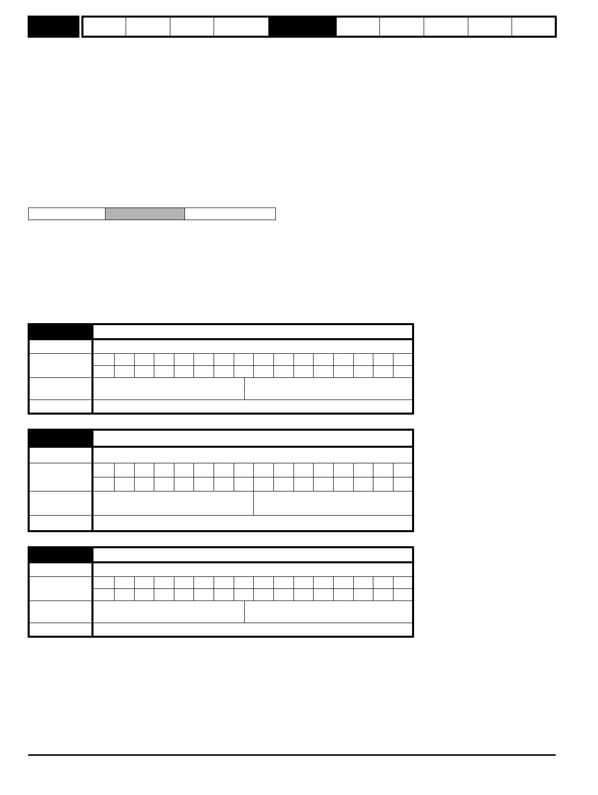
31 24 23 14 13 0
Turns information
Position Do not care
x.29 Non-marker reset revolution counter
Drive modes Open-loop, Closed-loop vector, Servo, Regen
Coding
Bit SP FI DE Txt VM DP ND RA NC NV PT US RW BU PS
111 1
Default
Open-loop, Closed-loop vector, Servo,
Regen
0 to 65,535 revolutions
Update rate 4ms write
x.30 Non-marker reset position
Drive modes Open-loop, Closed-loop vector, Servo, Regen
Coding
Bit SP FI DE Txt VM DP ND RA NC NV PT US RW BU PS
111 1
Range
Open-loop, Closed-loop vector, Servo,
Regen
0 to 65,535 (1/2
16
ths of a revolution)
Update rate 4ms write
x.31 Non-marker reset fine position
Drive modes Open-loop, Closed-loop vector, Servo, Regen
Coding
Bit SP FI DE Txt VM DP ND RA NC NV PT US RW BU PS
111 1
Range
Open-loop, Closed-loop vector, Servo,
Regen
0 to 65,535 (1/2
32
ths of a revolution)
Update rate 4ms write
http://nicontrols.com