Parameter
structure
Keypad and
display
Parameter
x.00
Parameter
description format
Advanced parameter
descriptions
Macros
Serial comms
protocol
Electronic
nameplate
Performance
Feature look-
up table
368 Unidrive SP Advanced User Guide
www.controltechniques.com Issue Number: 7
8 Electronic nameplate
The electronic nameplate system is a means of storing some specific
drive parameters within the EEPROM of a Stegmann or Heidenhain
encoder attached to the drive. The system used is similar to that used
with the MAx range electronic nameplate system. The parameters
stored in the encoder are in two categories: motor object parameters,
and performance object parameters.
Motor object parameters
The encoder can contain one motor object which holds parameters
related to the motor on which the encoder is fitted and the motor load.
Performance object parameters
The encoder can contain up to 2 performance objects each of which
contains a set of parameters that can be used to give different levels of
motor performance.
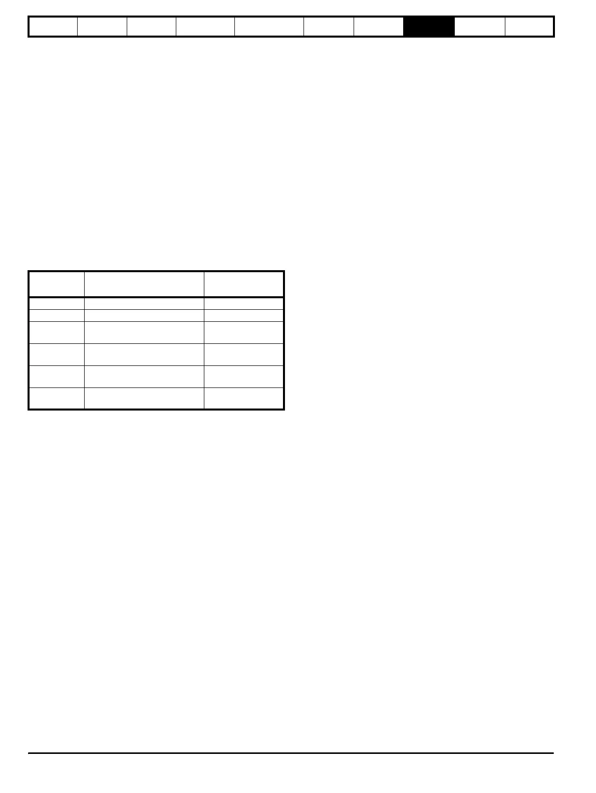
Loading/storing object parameters
Parameters may be transferred to or from the drive to a suitable encoder
attached to the drive or one of its Solutions Modules by entering a code
into Pr x.00 and then resetting the drive as shown in the table below. The
z in the request defines the location of the encoder for the transfer
(0=drive, 1=Solutions Module slot 1, etc.)
The motor object includes some data that does not normally have
associated parameters, but would be entered into the object by the
motor manufacturer. To allow this data to be transferred to an encoder
from a drive without additional equipment, Pr 18.11 to Pr 18.17 can be
used to transfer this data if Pr 3.49 is set to one.
It should be noted that the data within the objects in the encoder is
undefined until it has been written and that the manufacturer’s data is
undefined until it has been written by a complete motor object write with
Pr 3.49 set to one.
The tables given below show the motor and performance objects. For
HIPERFACE encoders the data block and the byte address within the
block is given. For EnDat encoders the data is stored as words in the
OEM parameter area at the addresses shown. (Byte 0 indicates LS
byte.)
The checksum for each object is Zero – sum of bytes in the object
excluding the checksum itself. The number of bytes defines the number
of bytes used to generate the checksum. This includes all the
parameters and the number of bytes parameter, and so this value will
always be 62 for the motor object and 30 for a performance object.
When either a motor or performance object is transferred to the drive all
drive parameters are saved. When a performance object is loaded the
speed control gain select parameter is automatically set to zero.
Therefore, either the speed controller gains defined in the performance
object or those derived from the compliance angle, bandwidth and
damping factor parameters are used.
Parameter
x.00 code
Data transferred Direction
110z0 Motor object parameters Drive to encoder
110z1 Motor object parameters Encoder to drive
110z2
Performance object block 1
parameters
Drive to encoder
110z3
Performance object block 1
parameters
Encoder to drive
110z4
Performance object block 2
parameters
Drive to encoder
110z5
Performance object block 2
parameters
Encoder to drive
http://nicontrols.com