Menu 6
Parameter
structure
Keypad and
display
Parameter
x.00
Parameter
description format
Advanced parameter
descriptions
Macros
Serial comms
protocol
Electronic
nameplate
Performance
Feature look-
up table
124 Unidrive SP Advanced User Guide
www.controltechniques.com Issue Number: 7
bus voltage above the detection threshold Vml
3
and the drive will continue to operate normally. The output of the mains loss controller is a current
demand that is fed into the current control system and therefore the gain parameters Pr 4.13 and Pr 4.14 must be set up for optimum control. See
Pr 4.13 and Pr 4.14 on page 95 for set-up details.
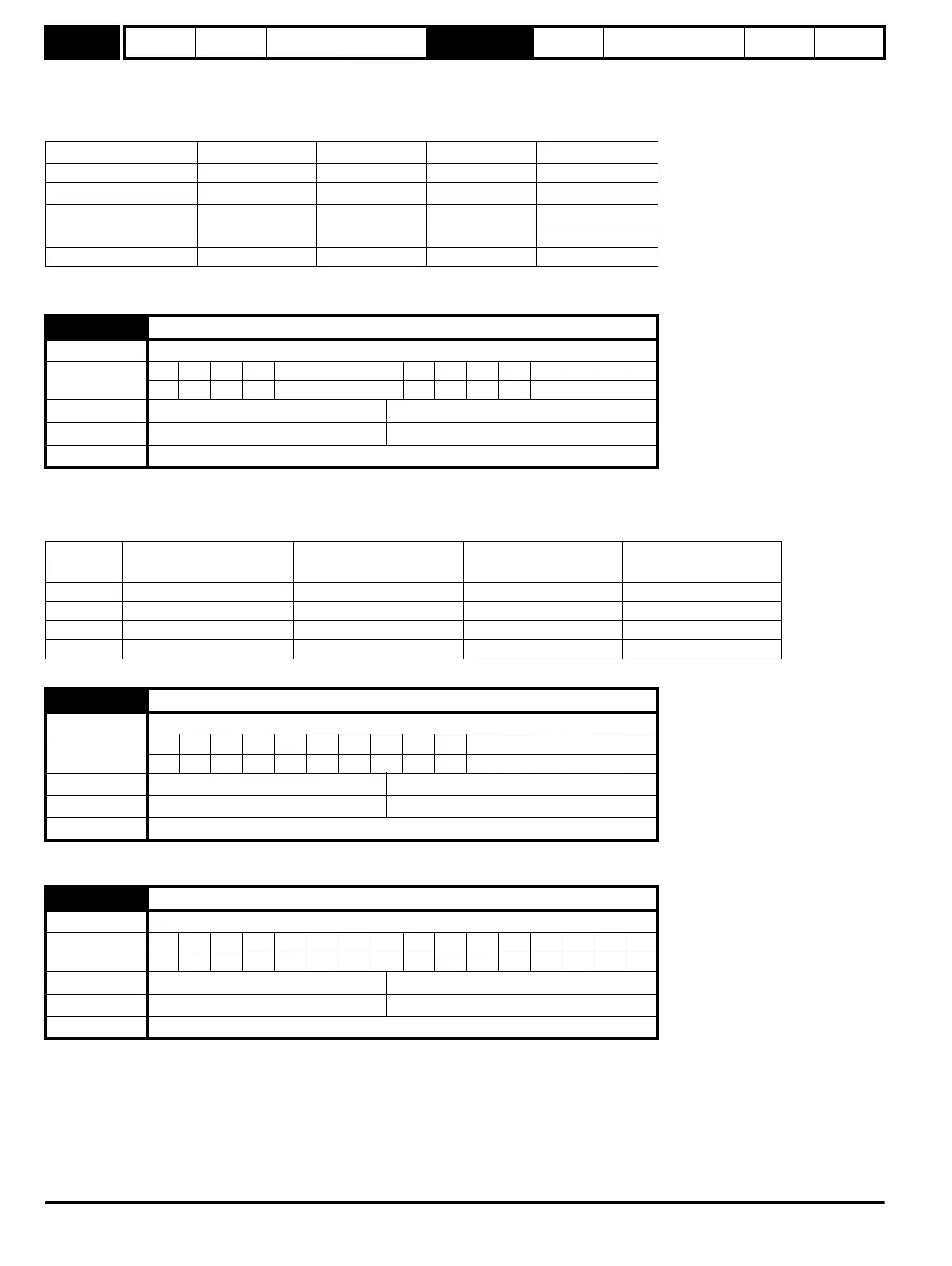
The following table shows the voltage levels used by drives with each voltage rating.
* Vml
1
is defined by Pr 6.48. The values given in the table are the default values.
This parameter is provided to allow the user to select several predefined digital input routing macros to control the sequencer. When a value between
0 and 3 is selected the drive processor continuously updates the destination parameters for digital I/O T25, T26 and T27, and the enable sequencer
latching bit (Pr 6.40). When a value of 4 is selected the destination parameters for these digital I/O and Pr 6.40 can be modified by the user. (Note any
changes made to the destination parameters only become active after a drive reset.)
Defines the current level used during DC injection braking as a percentage of motor rated current as defined by Pr 5.07.
Defines the time of injection braking during phase 1 with stopping modes 3 and 4 (see Pr 6.01 on page 123) for injection braking stop.
Voltage level 200V drive 400V drive 575V drive 690V drive
Vuu 175 330 435 435
Vml
1
205* 410* 540* 540*
Vml
2
Vml
1
- 10V Vml
1
- 20V Vml
1
- 25V Vml
1
- 25V
Vml
3
Vml
1
+ 10 Vml
1
+ 15 Vml
1
+ 50 Vml
1
+ 50
Vuu Restart 215 425 590 590
6.04 Start/stop logic select
Drive modes Open-loop, Closed-loop vector, Servo
Coding
BitSP FI DETEVMDPNDRANCNVPTUSRWBUPS
111
Range Open-loop, Closed-loop vector, Servo 0 to 4
Default Open-loop, Closed-loop vector, Servo 4
Update rate Background read
Pr 6.04 T25 T26 T27 Pr 6.40
0Pr 6.29 Pr 6.30 Run Forward Pr 6.32 Run Reverse 0 (non latching)
1Pr 6.39 Not stop Pr 6.30 Run Forward Pr 6.32 Run Reverse 1 (latching)
2Pr 6.29 Pr 6.34 Run Pr 6.33 Fwd /Rev 0 (non latching)
3Pr 6.39 Not stop Pr 6.34 Run Pr 6.33 Fwd/Rev 1 (latching)
4 User prog User prog User prog User prog
6.06 Injection braking level
Drive modes Open-loop
Coding
Bit SP FI DE TE VM DP ND RA NC NV PT US RW BU PS
1 1 111
Range Open-loop 0 to 150.0 %
Default Open-loop 100.0 %
Update rate Background read
6.07 Injection braking time
Drive modes Open-loop
Coding
BitSP FI DETEVMDPNDRANCNVPTUSRWBUPS
1 111
Range Open-loop 0.0 to 25.0 s
Default Open-loop 1.0
Update rate Background read
http://nicontrols.com