Menu 6
Parameter
structure
Keypad and
display
Parameter
x.00
Parameter
description format
Advanced parameter
descriptions
Macros
Serial comms
protocol
Electronic
nameplate
Performance
Feature look-
up table
130 Unidrive SP Advanced User Guide
www.controltechniques.com Issue Number: 7
In normal operation the sequencer has been designed to operate with Run forward / Run reverse controls, or with a Run control and a forward
reverse selector. If Run forwards / Run reverse control is required then bits Pr 6.30 and Pr 6.32 should be used to control the drive (digital inputs
should not be routed to bits Pr 6.33 and Pr 6.34). If Run control with a forward reverse selector is required then bits Pr 6.33 and Pr 6.34 should be
used to control the drive (digital inputs should not be routed to bits Pr 6.30 and Pr 6.32).
The Run forward and Run reverse, or Run sequencing bits can be made latching by setting bit Pr 6.40. The Not stop bit (Pr 6.39) should be one to
allow the sequencing bit to be latched. If the Not stop bit is zero all latches are cleared and held at zero. The jog or jog reverse sequencing bits can
also cause the drive to run provided the motor is stopped when these bits are activated and the normal run sequencing bits are not providing a run
signal.
Digital inputs connected to limit switches should be routed to these parameters if fast stopping is required at a limit. In Open-loop mode the drive will
respond in 4.5ms (500µs digital input filter delay + 4ms software delay) and stop the motor using the currently selected ramp rate. In Closed-loop
vector and Servo modes the drive will respond in 750µs (500µs digital input filter delay + 250µs software delay) and stop the motor with zero ramp
rate (i.e. in current limit). The limit switches are direction dependant so that the motor can rotate in a direction that allows the system to move away
from the limit switch. (In open-loop frequency slaving mode both limit switches are active.)
Open-loop
Pre-ramp reference > 0Hz Forward limit switch active
Pre-ramp reference < 0Hz Reverse limit switch active
Pre-ramp reference = 0Hz Both limit switches active
Closed-loop and Servo
Pre-ramp reference+hard speed reference > 0rpm Forward limit switch active
Pre-ramp reference+hard speed reference < 0rpm Reverse limit switch active
Pre-ramp reference+hard speed reference = 0rpm Both limit switches active
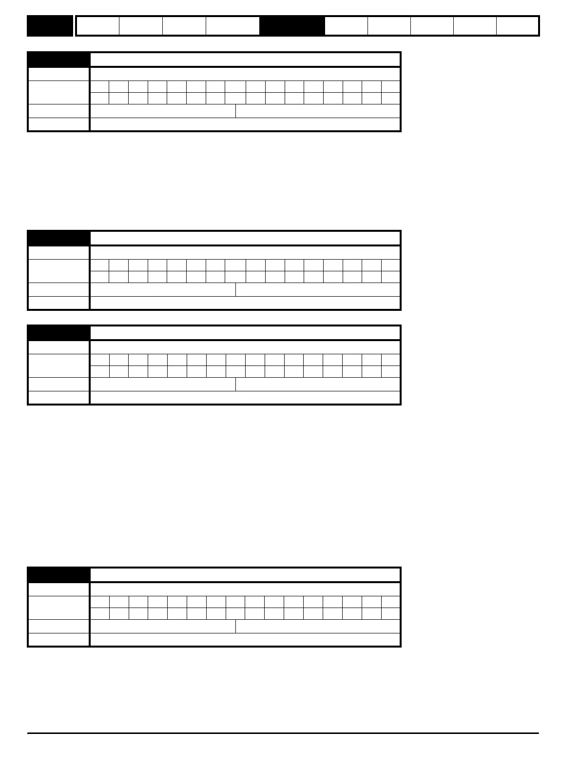
6.34 Sequencing bit: Run
Drive modes Open-loop, Closed-loop vector, Servo
Coding
Bit SP FI DE TE VM DP ND RA NC NV PT US RW BU PS
111
Default Open-loop, Closed-loop vector, Servo 0
Update rate 4ms read
6.35 Forward limit switch
Drive modes Open-loop, Closed-loop vector, Servo
Coding
Bit SP FI DE TE VM DP ND RA NC NV PT US RW BU PS
111
Default Open-loop, Closed-loop vector, Servo 0
Update rate 250µs read
6.36 Reverse limit switch
Drive modes Open-loop, Closed-loop vector, Servo
Coding
Bit SP FI DE TE VM DP ND RA NC NV PT US RW BU PS
111
Default Open-loop, Closed-loop vector, Servo 0
Update rate 250µs read
6.37 Sequencing bit: Jog reverse
Drive modes Open-loop, Closed-loop vector, Servo
Coding
Bit SP FI DE TE VM DP ND RA NC NV PT US RW BU PS
111
Default Open-loop, Closed-loop vector, Servo 0
Update rate 4ms read
http://nicontrols.com