Parameter
structure
Keypad and
display
Parameter
x.00
Parameter
description format
Advanced parameter
descriptions
Macros
Serial comms
protocol
Electronic
nameplate
Performance
Feature look-
up table
Menu 5
Unidrive SP Advanced User Guide 117
Issue Number: 7 www.controltechniques.com
High speed servo mode is not enabled as default. Care must be taken when using this mode with servo motors to avoid damaging the drive. The
voltage produced by the servo motor magnets is proportional to speed. For high speed operation the drive must apply currents to the motor to
counter-act the flux produced by the magnets. It is possible to operate the motor at very high speeds that would give a very high motor terminal
voltage, but this voltage is prevented by the action of the drive. If however, the drive is disabled (or tripped) when the motor voltages would be higher
than the rating of the drive without the currents to counter-act the flux from the magnets, it is possible to damage the drive. If high speed mode is
enabled the motor speed must be limited to the levels given in the table below unless an additional hardware protection system is used to limit the
voltages applied to the drive output terminals to a safe level.
Ke is the ratio between r.m.s. line to line voltage produced by the motor and the speed in V/rpm. Care must also be taken not to de-magnetise the
motor. The motor manufacturer should always be consulted before using this mode.
Due to various effects in the drive inverter a voltage offset must be produced before any current flows. To obtain good performance at low frequencies
where the machine terminal voltage is small this offset must be taken into account. The value shown in Pr 5.23 is this offset given in line to line rms
volts. It is not possible for the user to measure this voltage easily, and so the automatic measurement procedure should be used (see Pr 5.14 on page
114).
Open-loop, Closed-loop vector
With reference to the diagram overleaf, the transient inductance is defined as
σL
s
= L
1
+ (L
2
.L
m
/ (L
2
+ L
m
))
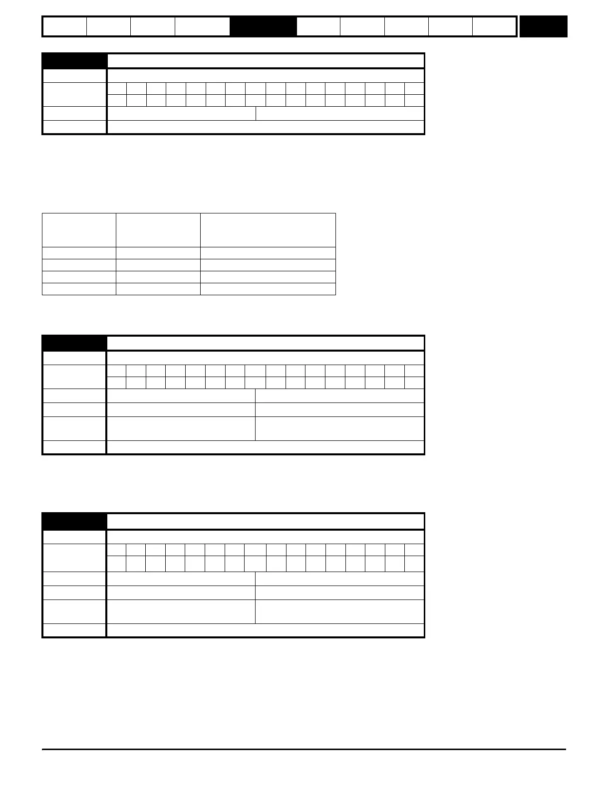
5.22 Enable high speed servo mode
Drive modes Servo
Coding
Bit SP FI DE Txt VM DP ND RA NC NV PT US RW BU PS
111
Default Servo 0
Update rate Background read
Drive voltage
rating
Maximum motor
speed
(rpm)
Maximum safe line to line voltage
at the motor terminals (V rms)
200 400 / (Ke x √2) 400 / √2
400 800 / (Ke x √2) 800 / √2
575 955 / (Ke x √2) 955 / √2
690 1145 / (Ke x √2) 1145 / √2
5.23 Voltage offset
Drive modes Open-loop
Coding
Bit SP FI DE Txt VM DP ND RA NC NV PT US RW BU PS
11 111
Range Open-loop 0.0 to 25.0 V
Default Open-loop 0.0
Second motor
parameter
Open-loop Pr 21.13
Update rate Background read
5.24
Transient inductance (σL
s
)
Drive modes Open-loop, Closed-loop vector, Servo
Coding
Bit SP FI DE Txt VM DP ND RA NC NV PT US RW BU PS
31 111
Range Open-loop, Closed-loop vector, Servo 0.000 to 500.000 mH
Default Open-loop, Closed-loop vector, Servo 0.000
Second motor
parameter
Open-loop, Closed-loop vector, Servo Pr 21.14
Update rate Background read
http://nicontrols.com