Menu 6
Parameter
structure
Keypad and
display
Parameter
x.00
Parameter
description format
Advanced parameter
descriptions
Macros
Serial comms
protocol
Electronic
nameplate
Performance
Feature look-
up table
134 Unidrive SP Advanced User Guide
www.controltechniques.com Issue Number: 7
and phase loss are detected from the input stage and can cause an ACUU.P or PH.P trip. It is possible to disable these trips by setting this parameter
to one. In most applications even where the drive is supplied via its d.c. power terminals this is not necessary as all the modules in a multi-module
system will indicate mains loss and hence no trip is initiated.
UNISP4xxx, UNISP5xxx, UNISP6xxx and UNISP7xxx drives, which all have an active input rectifier circuit, use the mains loss indication from this unit
to determine when the ACUU condition should end. If these drives are not supplied via the a.c. power terminals this feature can be disabled by setting
this parameter to one.
The mains loss detection level can be adjusted using this parameter. If the value is reduced below the default value the default value is used by the
drive. If the level is set too high so that mains loss detection becomes active under normal operating conditions the motor will coast to a stop.
When power modules are connected in parallel various trips can be initiated from the power modules themselves. To aid identification of the source of
the trip the module number of the source can be stored in the module number and trip time log (Pr 10.41 to Pr 10.51). If the drive is a single module
drive the module number that is stored is normally zero. However, a UNISP6xxx or UNISP7xxx drive can be fitted with the interface circuits normally
intended for parallel operation, but it is a single module drive. In this case a module number of 1 is stored.
If Pr 6.49 is zero the module number is stored in the module number and trip time log. If this parameter is one, either the powered-up clock or run time
clock is stored in the module number and trip time log as defined by Pr 6.28. It should be noted that changing this parameter clears the trip, and
module number and trip time logs.
The drive comms system 128 bytes buffer used with ANSI or Modbus rtu protocols via the 485 connector can be controlled by an option module
under certain circumstances. This parameter shows which node has control of the buffer (0 (drv) = drive, 1 (Slot1) = option module in slot 1, etc. If an
option module has control of the buffer the drive will use an alternative buffer for 485 comms and the following restrictions will apply:
1. Comms messages via the 485 port are limited to a maximum of 32 bytes
2. The 6 pin keypad port will operate correctly with an LED keypad, but it will no longer operate with an LCD keypad
3. Modbus messages using the CMP protocol can only route messages to nodes within the drive. It will not be possible for these to be routed further,
i.e. via CT Net on an SM Applications module.
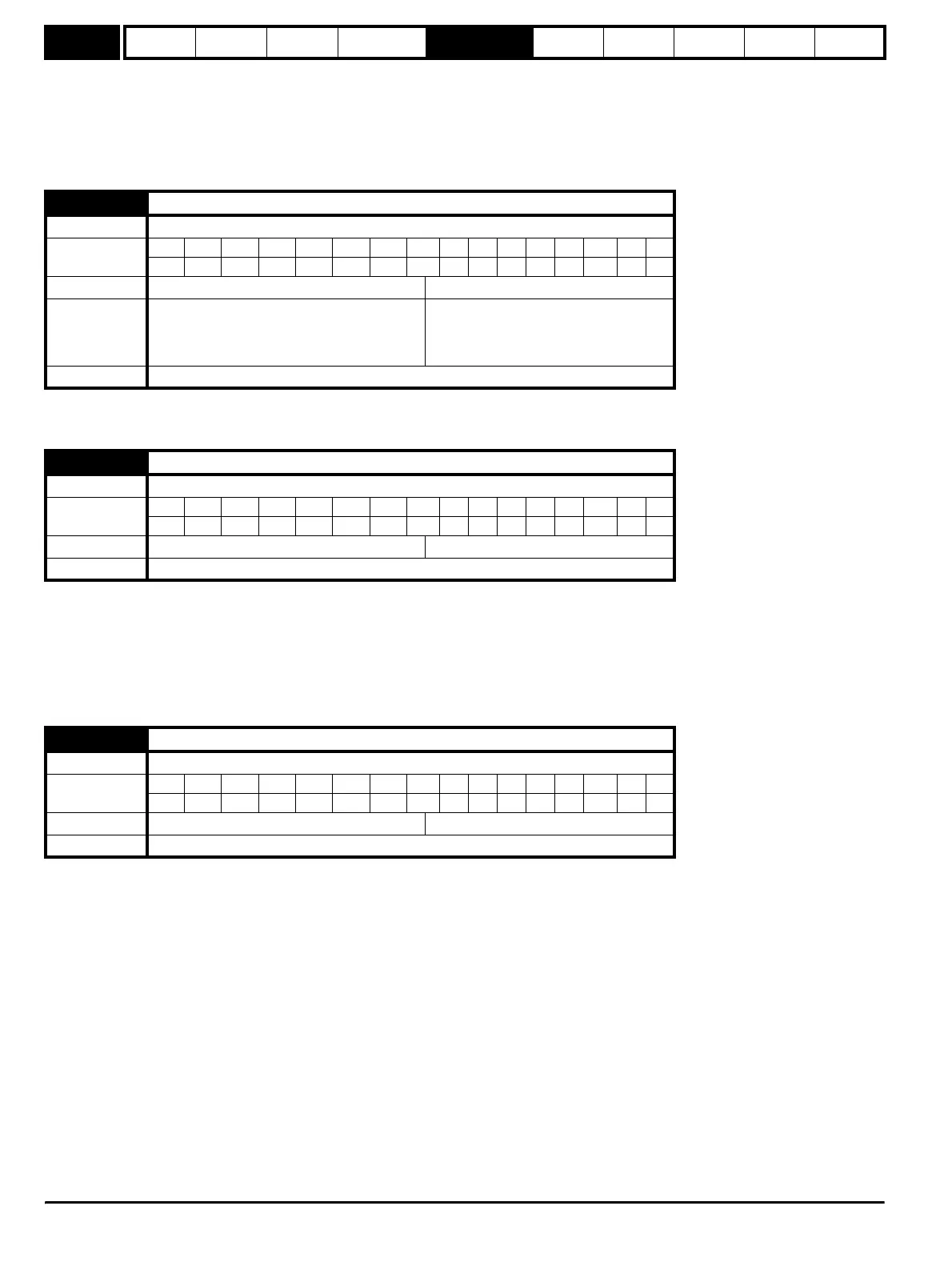
6.48 Mains loss ride through detection level
Drive modes Open-loop, Closed-loop vector, Servo, Regen
Coding
Bit SP FI DE TE VM DP NDRANCNVPTUSRWBUPS
1 1 111
Range Open-loop,Closed-loop vector, Servo 0 to DC_VOLTAGE_SET_MAX V
Default Open-loop,Closed-loop vector, Servo
200V rated drive 205
400V rated drive 410
575V rated drive 540
690V rated drive 540
Update rate Background read
6.49 Disable multi-module drive module number storing on trip
Drive modes Open-loop, Closed-loop vector, Servo, Regen
Coding
Bit SP FI DE TE VM DP NDRANCNVPTUSRWBUPS
111
Default Open-loop, Closed-loop vector, Servo, Regen 0
Update rate Background read
6.50 Drive comms state
Drive modes Open-loop, Closed-loop vector, Servo, Regen
Coding
Bit SP FI DE TE VM DP NDRANCNVPTUSRWBUPS
11111
Default , Open-loop,Closed-loop vector, Servo, Regen 0 to 3
Update rate Background write
http://nicontrols.com