Parameter
structure
Keypad and
display
Parameter
x.00
Parameter
description format
Advanced parameter
descriptions
Macros
Serial comms
protocol
Electronic
nameplate
Performance
Feature look-
up table
Menu 3
All modes
Unidrive SP Advanced User Guide 69
Issue Number: 7 www.controltechniques.com
Encoder power supply trips
The encoder power supply from the drive can be switched off by the drive either because the encoder power supply is overloaded (Enc1 trip) or
because the internal 24V supply within the drive is overloaded (PS.24V trip). The internal 24V supply provides power for the encoder power supply,
user 24V output, digital I/O, option modules etc. To ensure that an Enc1 trip is not initiated when the internal 24V is overloaded, and subsequently
switched off by the drive, there is a delay of 40ms in the detection of Enc1 trip. It is possible for other encoder trips such as wire break detection
(Enc2) to occur when the power supply is removed from the encoder. Therefore overloading the internal 24V supply or the encoder supply could
result in an immediate Enc2 trip. To ensure that the correct reason for the trip is given PS.24V and Enc1 trips override an existing Enc2 to Enc8or
Enc11 trip. This means that both the original trip (Enc2 to Enc8 or Enc11) and then the new trip (PS.24V or Enc1) are stored in the trip log.
SC.Hiper, SC.EnDat, EnDat
When a SC.Hiper, SC.EnDat or EnDat encoder is being used, the drive will interrogate the encoder on power-up. If Pr 3.41 is set to one and the
encoder type is recognised based on the information provided by the encoder, the drive will set the encoder turns / linear encoder comms to sine
wave ratio (Pr 3.33), the equivalent lines per revolution (Pr 3.34) and the encoder comms resolution / linear encoder comms bits (Pr 3.35). For
SC.Hiper or SC.EnDat encoders the rotary encoder select (Pr 3.39) is also set up. If the encoder is not recognised, there is a comms error or the
resulting parameter values are out of range the drive initiates an Enc7 or Enc12 to Enc17 trip to prompt the user to enter the information. The drive
can auto-configure with any of the following devices.
Rotary EnDat encoders
The encoder turns, comms resolution and equivalent lines per rev are set up directly using the data read from the encoder.
Linear EnDat encoders
The comms resolution is set to the number of bits required for the whole position within the position data messages from the encoder. The linear
encoder comms to sine wave ratio is calculated from the sine wave period and LS comms bit length. The encoder does not give the equivalent lines
per rev directly, but gives the length of a sinewave period in nm. Therefore the drive uses the pole pitch (Pr 5.36 or 21.31) and the number of motor
poles (Pr 5.11 or 21.11) for the current active motor (defined by Pr 11.45) to calculate the equivalent lines per revolution.
ELPR = Pole pitch x Number of motor pole pairs / Length of a sinewave
Normally the Number of motor poles will be set to 2, and so
ELPR = Pole pitch / Length of a sinewave
It should be noted that the equivalent lines per rev parameter is only updated when auto-configuration occurs, i.e. when the encoder is initialised, and
that it uses the pole pitch for the currently active motor. The value for Pole pitch x Number of motor pole pairs is limited to 655.35mm by the drive. If
the pole pitch is left at its default value of zero which would give ELPR = 0, or the result of the calculation is over 50000, the drive will initiate an
EnC15 trip.
Hiperface encoders
The drive can recognise any of the following devices: SCS 60/70, SCM 60/70, SRS 50/60, SRM 50/60, SHS 170, LINCODER, SCS-KIT 101, SKS36,
SKM36. If the drive cannot recognise the encoder type it will initiate EnC12 trip.
SSI, SC.SSI
SSI encoders normally use gray code data format. However, some encoders use binary format which may be selected by setting this parameter to
one.
0 = 0ms, 1 = 1ms, 2 = 2ms, 3 = 4ms, 4 = 8ms, 5 = 16ms
Encoder type Initialisation delay
Ab, Fd, Fr, Ab.Servo,
Fd.Servo, Fr.Servo
None
SC.Hiper 150ms
SC.EnDat, EnDat 1.0s
All other types 1.2s
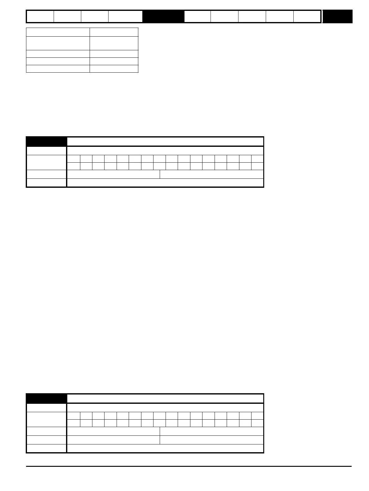
3.41
Drive encoder auto configuration enable / SSI binary format select
Drive modes Open-loop, Closed-loop vector, Servo
Coding
Bit SP FI DE Txt VM DP ND RA NC NV PT US RW BU PS
1 111
Default Open-loop, Closed-loop vector, Servo 0
Update rate Background read
3.42
Drive encoder filter
Drive modes Open-loop, Closed-loop vector, Servo
Coding
Bit SP FI DE Txt VM DP ND RA NC NV PT US RW BU PS
111
Range Open-loop, Closed-loop vector, Servo 0 to 5 (0 to16 ms)
Default Open-loop, Closed-loop vector, Servo 0
Update rate Background read
http://nicontrols.com