Menu 7
Parameter
structure
Keypad and
display
Parameter
x.00
Parameter
description format
Advanced parameter
descriptions
Macros
Serial comms
protocol
Electronic
nameplate
Performance
Feature look-
up table
142 Unidrive SP Advanced User Guide
www.controltechniques.com Issue Number: 7
The following modes are available for the analog outputs.
If high speed update mode is selected and the source for the output is one of the parameters designated for high speed analog output operation (see
start of this section) the output is updated at a higher rate with special scaling. If the parameter selected is not designated for this mode the output is
updated at the normal rate. If speed feedback or power is selected for high speed mode for both analog output 1 and analog output 2 the setting is
ignored for analog output 2. If the high speed mode is selected the output is always a voltage signal.
Setting this bit will cause the drive to re-calibrate the full scale level of analog input 1 provided the input voltage is below +1.5V or above +2.5V. This
parameter is cleared by the software automatically when the calibration is complete. If the input voltage is above +2.5V the input voltage itself is used
for calibration, and so after calibration this level will be full scale for the input. If the input voltage is below +1.5V the internal reference is used for
calibration, and so the full scale will be nominally 9.8V after calibration. The calibration level is automatically stored on power-down. It should be noted
that the Analog input 1 offset trim is included in the input voltage when the input voltage itself is used for calibration, but this trim is not included when
the internal reference is used for calibration.
Analog input 1 is filtered using a window filter to remove quantisation noise and adjust the resolution of this input. The length of the window can be
adjusted with this parameter. The shortest possible window is 250µs. It should be noted that if this input is not used as a speed reference (Pr 1.36, Pr
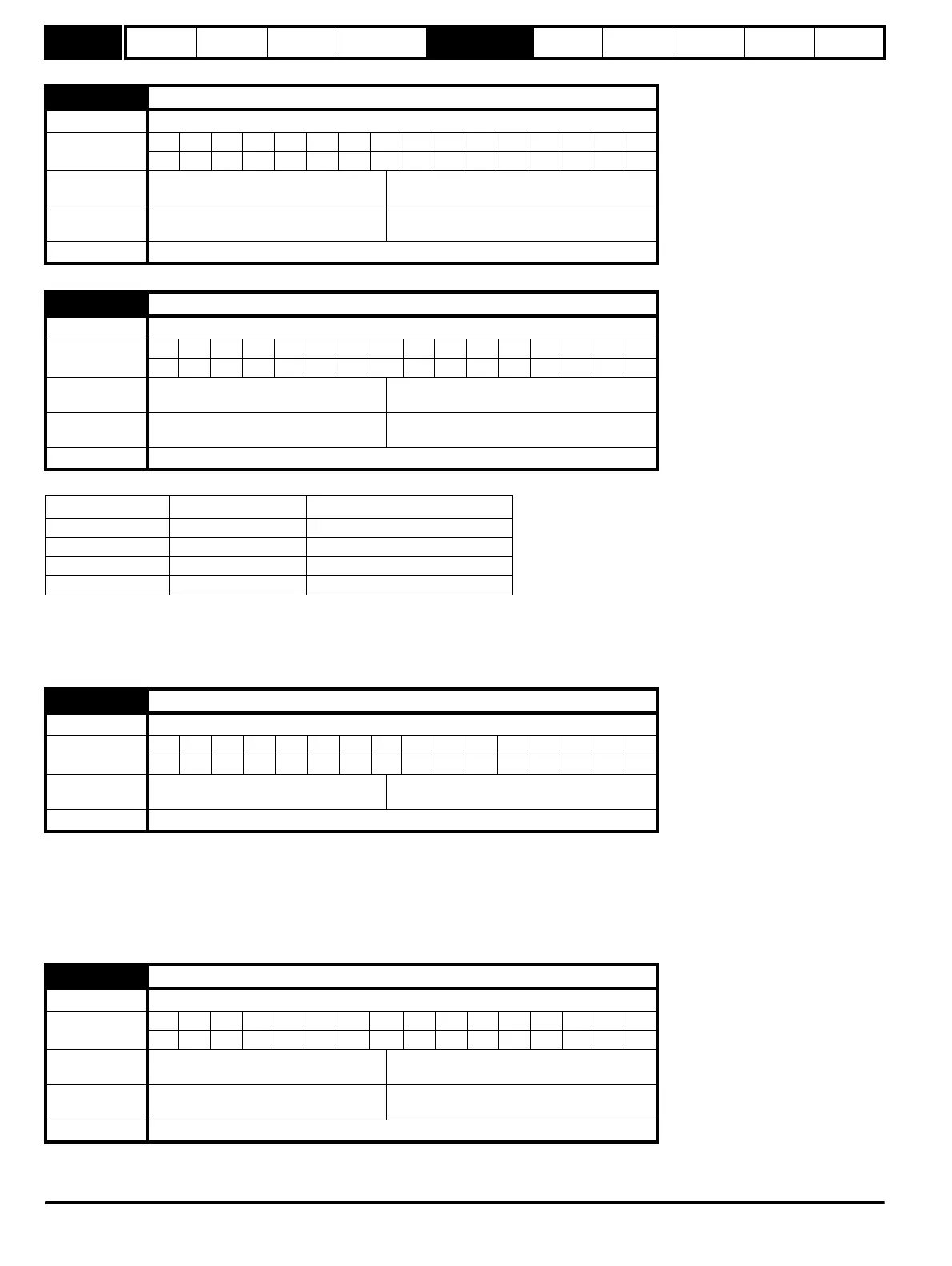
7.23 T10 analog output 2 scaling
Drive modes Open-loop, Closed-loop vector, Servo, Regen
Coding
Bit SP FI DE Txt VM DP ND RA NC NV PT US RW BU PS
3111
Range
Open-loop, Closed-loop vector, Servo,
Regen
0.000 to 4.000
Default
Open-loop, Closed-loop vector, Servo,
Regen
1.000
Update rate Background read
7.24 T10 analog output 2 mode
Drive modes Open-loop, Closed-loop vector, Servo, Regen
Coding
Bit SP FI DE Txt VM DP ND RA NC NV PT US RW BU PS
1 111
Range
Open-loop, Closed-loop vector, Servo,
Regen
0 to 3
Default
Open-loop, Closed-loop vector, Servo,
Regen
0
Update rate Background read
Parameter value Parameter string Mode
0 VOLt Voltage mode
10-20 0 - 20mA
24-20 4 - 20mA
3 H.Spd High speed up date mode
7.25 Calibrate T5/6 analog input 1 full scale
Drive modes Open-loop, Closed-loop vector, Servo, Regen
Coding
Bit SP FI DE Txt VM DP ND RA NC NV PT US RW BU PS
111
Default
Open-loop, Closed-loop vector, Servo,
Regen
0
Update rate Background read
7.26 T5/6 analog input 1 sample time
Drive modes Open-loop, Closed-loop vector, Servo, Regen
Coding
Bit SP FI DE Txt VM DP ND RA NC NV PT US RW BU PS
1111
Range
Open-loop, Closed-loop vector, Servo,
Regen
0 to 8.0 ms
Default
Open-loop, Closed-loop vector, Servo,
Regen
4.0
Update rate Background read
http://nicontrols.com