Menu 3
Closed-loop
Parameter
structure
Keypad and
display
Parameter
x.00
Parameter
description format
Advanced parameter
descriptions
Macros
Serial comms
protocol
Electronic
nameplate
Performance
Feature look-
up table
58 Unidrive SP Advanced User Guide
www.controltechniques.com Issue Number: 7
The bandwidth is defined as the theoretical 3dB point on the closed-loop gain characteristic of the speed controller as a second order system. At this
point the phase shift is approximately 60°. This parameter is used to define the bandwidth used for setting up the speed loop gain parameters
automatically when Pr 3.17 = 1.
This is the damping factor related to the response of the system to a torque transient, and so if the damping factor is unity the response to a load
torque transient is critically damped. The step response of the speed controller gives approximately 10% overshoot with unity damping factor.
This parameter is used to define the damping factor used for setting up the speed loop gain parameters automatically when Pr 3.17 = 1 or 2
.
The hard speed reference is a reference value which does not pass through the ramp system (Menu 2). It is added to the normal post ramp speed
reference. Its value may be written from the keypad, via serial comms, from an analog input or from an encoder input. This parameter can also be
used by the position controller (Menu 13) as the speed reference input. The hard speed reference is selected when Pr 3.23 = 1.
0: Closed-loop vector mode with position feedback
The drive uses the closed-loop vector algorithm with the selected position feedback.
1: Closed-loop vector mode without position feedback
The drive uses the closed-loop vector algorithm and derives the position feedback internally.
2: Closed-loop vector mode with no maximum speed limit
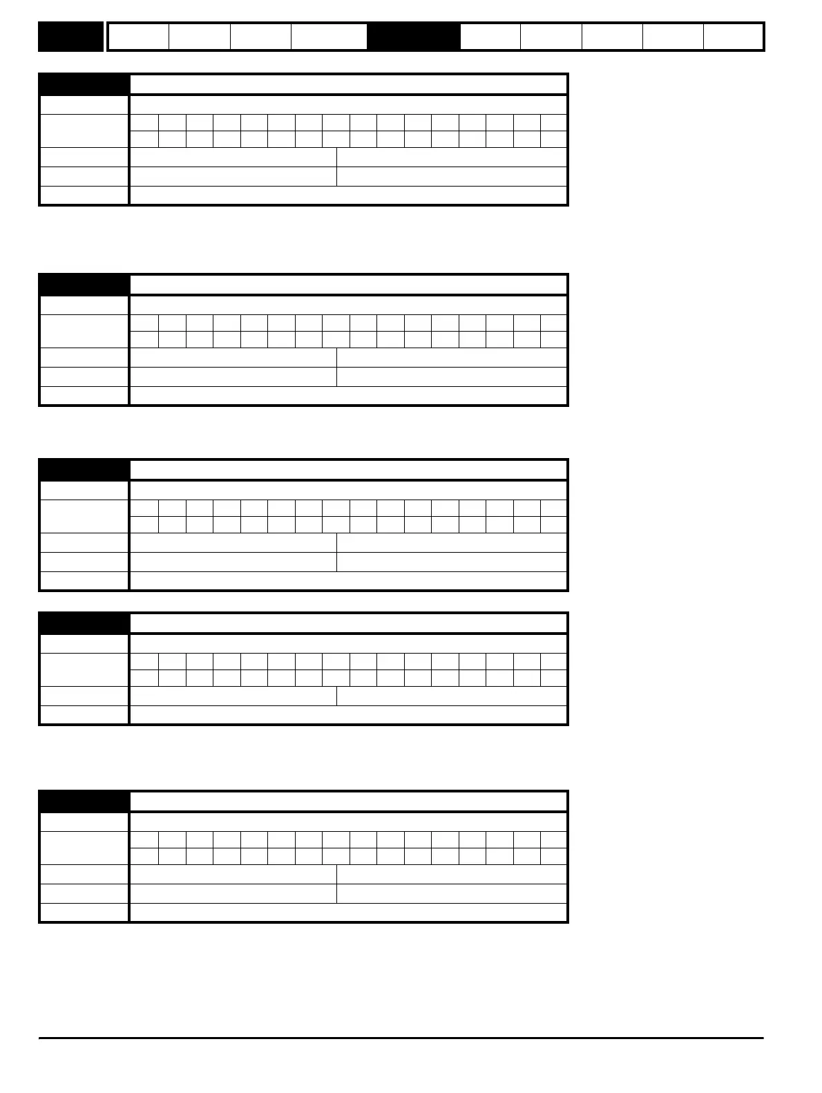
3.20
Bandwidth
Drive modes Closed-loop vector, Servo
Coding
Bit SP FI DE Txt VM DP ND RA NC NV PT US RW BU PS
111
Range Closed-loop vector, Servo 0 to 255 Hz
Default Closed-loop vector, Servo 10 Hz
Update rate Background (1s) read
3.21
Damping factor
Drive modes Closed-loop vector, Servo
Coding
Bit SP FI DE Txt VM DP ND RA NC NV PT US RW BU PS
1111
Range Closed-loop vector, Servo 0.0 to 10.0
Default Closed-loop vector, Servo 1.0
Update rate Background (1s) read
3.22
Hard speed reference
Drive modes Closed-loop vector, Servo
Coding
Bit SP FI DE Txt VM DP ND RA NC NV PT US RW BU PS
11 111
Range Closed-loop vector, Servo ±SPEED_FREQ_MAX rpm
Default Closed-loop vector, Servo 0.0
Update rate 4ms read
3.23
Hard speed reference selector
Drive modes Closed-loop vector, Servo
Coding
Bit SP FI DE Txt VM DP ND RA NC NV PT US RW BU PS
111
Default Closed-loop vector, Servo 1
Update rate 4ms read
3.24
Closed-loop vector mode
Drive modes Closed-loop vector
Coding
Bit SP FI DE Txt VM DP ND RA NC NV PT US RW BU PS
111
Range Closed-loop vector 0 to 3
Default Closed-loop vector 0
Update rate Background read
http://nicontrols.com