Parameter
structure
Keypad and
display
Parameter x.00
Parameter
description format
Advanced parameter
descriptions
Macros
Serial comms
protocol
Electronic
nameplate
Performance
Feature look-
up table
20 Unidrive SP Advanced User Guide
www.controltechniques.com Issue Number: 7
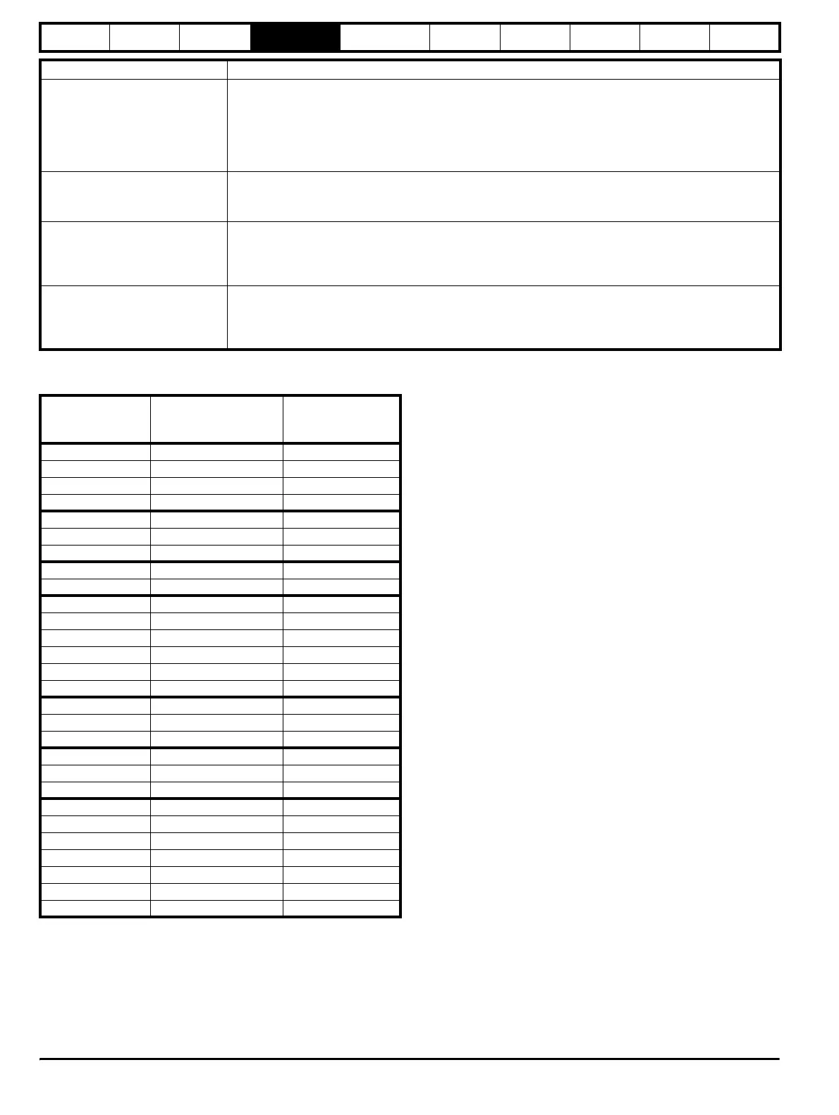
Table 4-2 Maximum motor rated current
Default
The default values given are the standard drive defaults which are
loaded after a drive reset with 1233 in Pr x.00.
Second motor parameter
Some parameters have an equivalent second motor value that can be
used as an alternative when the second motor is selected with Pr 11.45.
Menu 21 contains all the second motor parameters. In this menu the
parameter specifications include the location of the normal motor
parameter which is being duplicated.
Update rate
Defines the rate at which the parameter data is written by the drive
(write) or read and acted upon by the drive (read). Where background
update rate is specified, the update time depends on the drive processor
load. Generally the update time is between 2ms and 30ms, however, the
update time is significantly extended when loading defaults, changing
drive mode, transferring data to/from a SMARTCARD, or transferring
blocks of parameters or large CMP data blocks to/from the drive (not a
Solutions Module) via the drive serial comms port.
4.2 Sources and destinations
Sources
Some functions have source parameters, i.e. drive outputs, PID
controller etc. The source parameter range is Pr 0.00 to Pr 21.51.
1. If the source parameter does not exist the input is taken as zero.
2. The input is given by (source value x 100%) / source parameter
maximum.
Destinations
Some functions have destination parameters, i.e. drive inputs, etc. The
destination parameter range is Pr 0.00 to Pr 21.51.
1. If the destination parameter does not exist then the output value has
no effect.
2. If the destination parameter is protected then the output value has
no effect.
3. If the function output is a bit value (i.e. a digital input) the destination
value is either 0 or 1 depending on the state of the function output. If
the function output is not a bit value (i.e. analog input) the
destination value is given by (function output x destination
parameter maximum) / 100%. Pr 1.36 and Pr 1.37 are a special
case. The scaling shown in the description of Pr 1.08 is used when
any non-bit type quantity is routed to these parameters.
4. If more than one destination selector is routed to the same
destination, the value of the destination parameter is undefined. The
drive checks for this condition where the destinations are defined in
any menu except menus 15 to 17. If a conflict occurs a dESt trip
occurs that cannot be reset until the conflict is resolved.
Sources and destinations
1. Bit and non-bit parameters may be connected to each other as
sources or destinations. The maximum for bit parameters is taken as
one.
2. All new source and destination routing only changes to new set-up
locations when the drive is reset.
AC_VOLTAGE_MAX
[930V]
Maximum AC output voltage
This maximum has been chosen to allow for maximum AC voltage that can be produced by the drive including
quasi-square wave operation as follows:
AC_VOLTAGE_MAX = 0.78 x DC_VOLTAGE_MAX
200V drives: 325V, 400V drives: 650V
575V drives: 780V, 690V drives: 930V
DC_VOLTAGE_SET_MAX
[1150V]
Maximum DC voltage set-point
200V rating drive: 0 to 400V, 400V rating drive: 0 to 800V
575V rating drive: 0 to 950V, 690V rating drive: 0 to 1150V
DC_VOLTAGE_MAX
[1190V]
Maximum DC bus voltage
The maximum measurable DC bus voltage.
200V drives: 415V, 400V drives: 830V
575V drives: 995V, 690V drives: 1190V
POWER_MAX
[9999.99kW]
Maximum power in kW
The maximum power has been chosen to allow for the maximum power that can be output by the drive with
maximum AC output voltage, maximum controlled current and unity power factor. Therefore
POWER_MAX = √3 x AC_VOLTAGE_MAX x RATED_CURRENT_MAX x 1.75
The values given in square brackets indicate the absolute maximum value allowed for the variable maximum.
Maximum Definition
Model
Maximum Heavy Duty
current rating (Pr
11.32)
Maximum Normal
Duty current rating
SP1201 4.3 5.2
SP1202 5.8 6.8
SP1203 7.5 9.6
SP1204 10.6 11
SP2201 12.6 15.5
SP2202 17 22
SP2203 25 28
SP3201 31 42
SP3202 42 54
SP1401 2.1 2.8
SP1402 3 3.8
SP1403 4.2 5.0
SP1404 5.8 6.9
SP1405 7.6 8.8
SP1406 9.5 11
SP2401 13 15.3
SP2402 16.5 21
SP2403 25 29
SP3401 32 35
SP3402 40 43
SP3403 46 56
SP3501 4.0 5.4
SP3502 5.4 6.1
SP3503 6.1 8.4
SP3504 9.5 11
SP3505 12 16
SP3506 18 22
SP3507 22 27
http://nicontrols.com