Parameter
structure
Keypad and
display
Parameter
x.00
Parameter
description format
Advanced parameter
descriptions
Macros
Serial comms
protocol
Electronic
nameplate
Performance
Feature look-
up table
Menu 6
Unidrive SP Advanced User Guide 125
Issue Number: 7 www.controltechniques.com
When this bit is set the drive remains active even when the run command has been removed and the motor has reached standstill. The drive goes to
the 'StoP' state instead of the 'rdy' state.
Open-loop
When the drive is enabled with this parameter at zero, the output frequency starts at zero and ramps to the required reference. When the drive is
enabled with this parameter at a non-zero value, the drive performs a start-up test to determine the motor speed and then sets the initial output
frequency to the synchronous frequency of the motor. The test is not carried out, and the motor frequency starts at zero, if the run command is given
when the drive is in the stop state, or when the drive is first enabled after power-up with Ur_I voltage mode, or when the run command is given with
Ur_S voltage mode. With default parameters the length of the test is approximately 250ms, however, if the motor has a long rotor time constant
(usually large motors) it may be necessary to extend the test time. The drive will do this automatically if the motor parameters including the rated load
rpm are set up correctly for the motor.
For the test to operate correctly it is important that the stator resistance (Pr 5.17, Pr 21.12) is set up correctly. This applies even if fixed boost (Fd) or
square law (SrE) voltage mode is being used. The test uses the rated magnetising current of the motor during the test, therefore the rated current (Pr
5.07, Pr 21.07 and Pr 5.10, Pr 21.10) and power factor should be set to values close to those of the motor, although these parameters are not as
critical as the stator resistance.
It should be noted that a stationary lightly loaded motor with low inertia may move slightly during the test. The direction of the movement is undefined.
Restrictions may be placed on the direction of this movement and on the frequencies detected by the drive as follows:
Closed-loop vector and Servo
When the drive is enabled with this bit at zero, the post ramp reference (Pr 2.01) starts at zero and ramps to the required reference. When the drive is
enabled with this parameter at one, the post ramp reference is set to the motor speed.
This parameter permanently enables the Stop key on the drive such that the drive will always stop when the Stop key is pressed. If keypad mode is
selected this has no effect because the Stop key is automatically enabled.
The sequencer logic has been designed so that pressing the Stop key, whether the Stop key is enabled or not, does not make the drive change from
a stopped to a running condition. As the Stop key is also used to reset trips this means that if the Stop key is pressed when the drive is tripped, the trip
will be reset, but the drive does not start. This is done as follows.
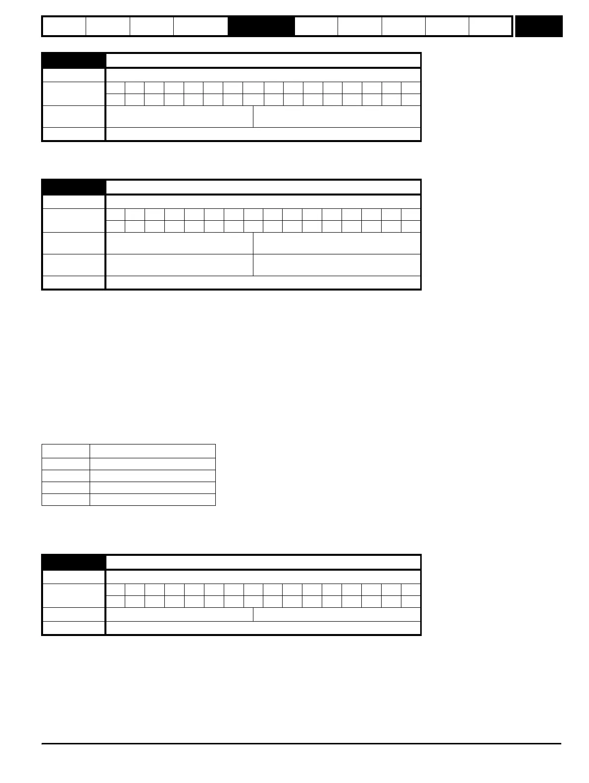
6.08 Hold zero speed
Drive modes Open-loop, Closed-loop vector, Servo
Coding
BitSP FI DETEVMDPNDRANCNVPTUSRWBUPS
111
Default
Open-loop, Closed-loop vector
Servo
0
1
Update rate 4ms read
6.09 Catch a spinning motor
Drive modes Open-loop, Closed-loop vector, Servo
Coding
Bit SP FI DE TE VM DP ND RA NC NV PT US RW BU PS
111
Range
Open-loop
Closed-loop vector, Servo
3
1
Default
Open-loop
Closed-loop vector, Servo
0
1
Update rate Background read
Pr 6.09 Function
0 Disabled
1 Detect all frequencies
2 Detect positive frequencies only
3 Detect negative frequencies only
6.12 Enable stop key
Drive modes Open-loop, Closed-loop vector, Servo
Coding
Bit SP FI DE TE VM DP ND RA NC NV PT US RW BU PS
111
Default Open-loop, Closed-loop vector, Servo 0
Update rate Background read
http://nicontrols.com