Parameter
structure
Keypad and
display
Parameter x.00
Parameter
description format
Advanced parameter
descriptions
Macros
Serial comms
protocol
Electronic
nameplate
Performance
Feature look-
up table
364 Unidrive SP Advanced User Guide
www.controltechniques.com Issue Number: 7
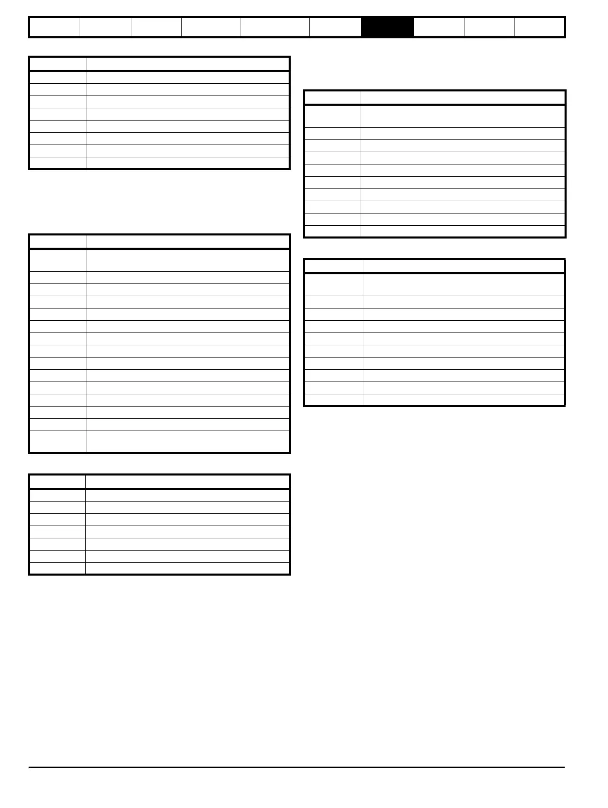
Table 7-6 Slave response
FC23 Read/Write multiple
Writes and reads two contiguous arrays of registers. The slave imposes
an upper limit on the number of registers which can be written. If this is
exceeded the slave will discard the request and the master will time out.
Table 7-7 Master request
Table 7-8 Slave response
FC64 CMP
Encapsulated CMP protocol. This non-standard function code is used to
transfer the CT standard CTNet Message Protocol (CMP).
Table 7-9 Master request
Table 7-10 Slave response
7.2.7 FC64 message routing capability
The FC64 encapsulated protocol includes extra destination fields to be
used for message routing between nodes on different networks. The
combination of Slave Node Address, CMP Destination Port and CMP
Destination Sub-Node Address allow a RTU slave to decide whether to
process a received message or retransmit the message through another
port onto a different communications network. When a node receives a
message addressed to itself (Slave Node Address matches the actual
node address), if the CMP Destination Port has the value 0, the nodes
processes the message locally; if the CMP Destination Port is non-zero,
the node should attempt to re-transmit the message to another node.
While particular implementations may vary, this section uses an example
to illustrate how the extra destination port and sub-node addresses can
be used to enable message routing.
Unidrive SP / SM-Applications Message Routing Example
Unidrive SP can hold up to three options in slots 1, 2 or 3. For the
purposes of message routing, these slots are treated as ports 1, 2 and 3
on Unidrive SP.
The Unidrive SP/ SM-Applications combination message routing falls
into 2 categories:
1. Routing of a CT Modbus RTU by Unidrive SP to a SM-Applications
in one of the Unidrive SP options slots.
In this example, a PC wishes to communicate with a SM-
Applications option located in option slot Y (where Y = 1, 2 or 3) in a
Unidrive SP with node address X on an RS485 network.
The PC sets the Slave Node Address to X, the CMP Destination Port
to Y and the CMP Destination Sub-Node Address field to 0 in the CT
Modbus RTU message and transmits the message over an RS485
network connecting the PC and Unidrive SP.
The Unidrive SP receives the message and notices that the CMP
Destination Port has the value Y - Unidrive SP does not process the
Byte Description
0 Slave source node address
1 Function code 0x10
2 Start register address MSB
3 Start register address LSB
4 Number of 16bit registers written MSB
5 Number of 16bit registers written LSB
6 CRC LSB
7 CRC MSB
Byte Description
0
Slave node address 1 through 247
0 is global
1 Function code 0x17
2 Start register address to read MSB
3 Start register address to read LSB
4 Number of 16bit registers to read MSB
5 Number of 16bit registers to read LSB
6 Start register address to write MSB
7 Start register address to write LSB
8 Number of 16bit registers to write MSB
9 Number of 16bit registers to write LSB
10 Length of register data to write (in bytes)
11 Register data 0 MSB
12 Register data 0 LSB
11+byte count CRC LSB
12+byte
count
CRC MSB
Byte Description
0 Slave source node address
1 Function code 0x17
2 Length of register data in read block (in bytes)
3 Register data 0 MSB
4 Register data 0 LSB
3+byte count CRC LSB
4+byte count CRC MSB
Byte Description
0
Slave node address 1 through 247
0 is global
1 Function code 0x40
2 CMP destination port
3 CMP destination sub-node address
4 CMP opcode
5 CMP status
6CMP PID
7 CMP data field of 'n' bytes
7+n CRC LSB
8+n CRC MSB
Byte Description
0
Slave node address 1 through 247
0 is global
1 Function code 0x40
2 CMP source port
3 CMP source sub node address
4 CMP opcode
5CMP status
6CMP PID
7 CMP data field of 'n' bytes
7+n CRC LSB
8+n CRC MSB
http://nicontrols.com