Parameter
structure
Keypad and
display
Parameter
x.00
Parameter
description format
Advanced parameter
descriptions
Macros
Serial comms
protocol
Electronic
nameplate
Performance
Feature look-
up table
Menu 3
Closed-loop
Unidrive SP Advanced User Guide 59
Issue Number: 7 www.controltechniques.com
3: Closed-loop vector mode without position feedback with no maximum speed limit
In some applications using closed-loop vector control the maximum speed of the system is above the speed at which the encoder feedback
frequency is too high to be used by the drive. For these type of applications Pr 3.24 should be set to 2 for low speed operation and 3 for high
speed operation. It should be noted that the drive no longer checks that the maximum encoder frequency cannot be exceeded in closed-loop
vector control, and so the user must ensure that Pr 3.24 is set to 3 before the encoder frequency limit is reached.
If the drive encoder lines per rev (Pr 3.34) is set to a value that is not a power of 2 and the drive encoder type (Pr 3.38) is used to select any type
of SINCOS encoder this parameter is forced to zero. This is because the extra processing time required to support the feedback device would not
allow enough time for the closed- loop vector algorithm without position feedback to be executed. It should be noted that if the algorithm without
position feedback is active that the sample rate for 6 and 12kHz operation is reduced from 12kHz to 6kHz (see Pr 5.37).
The phase angle between the rotor flux in a servo motor and the encoder position is required for the motor to operated correctly. If the phase angle is
known it can be set in this parameter by the user. Alternatively the drive can automatically measure the phase angle by performing a phasing test (see
Pr 5.12 on page 109). When the test is complete the new value is written to this parameter. The encoder phase angle can be modified at any time and
becomes effective immediately. This parameter has a factory default value of 0.0, but is not affected when defaults are loaded by the user.
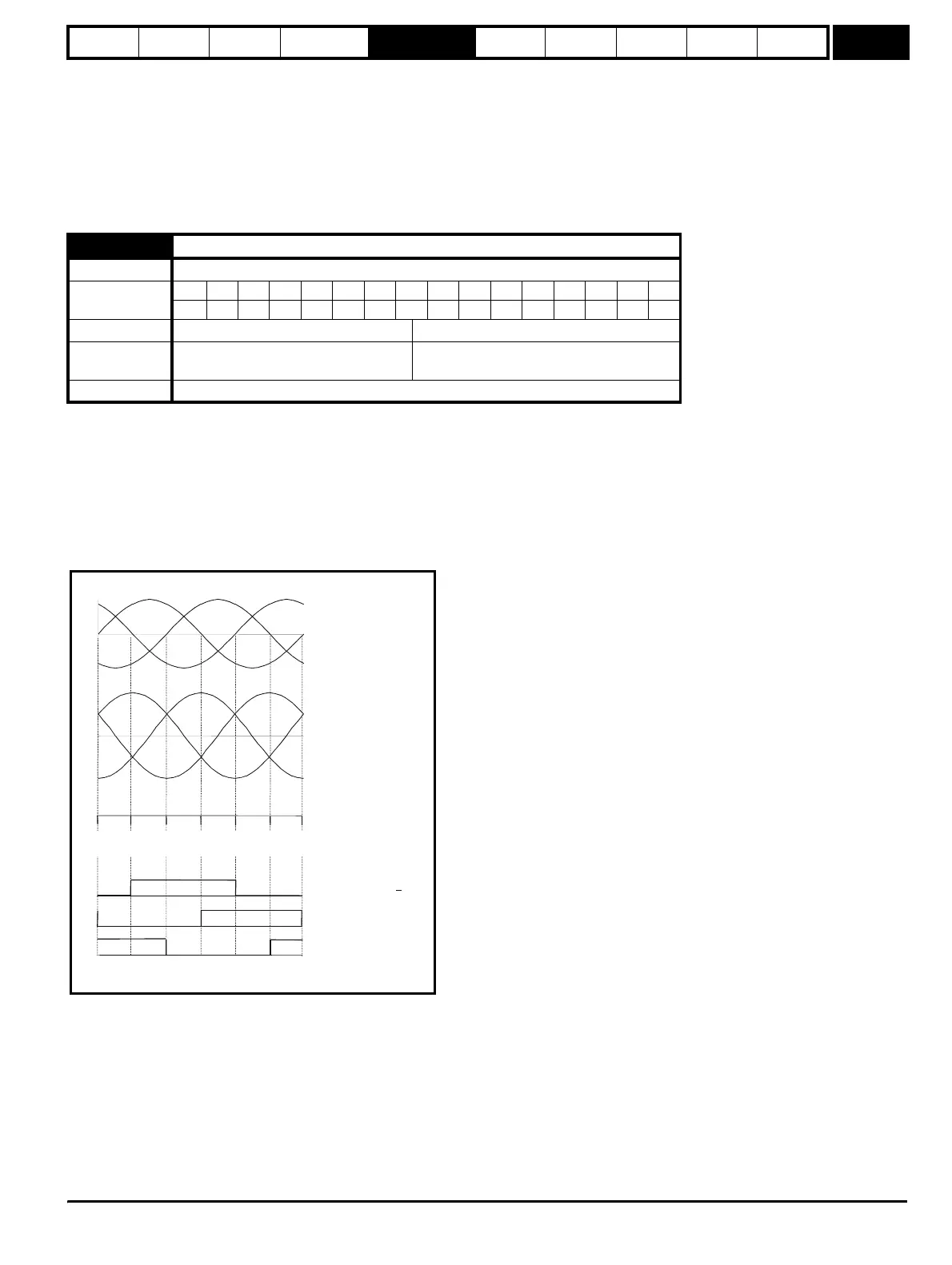
The alignment required for zero encoder phase angle (i.e. Pr 3.25 = 0.0) is given below for different feedback devices. Forward rotation of the motor
is produced when Vu leads Vv leads Vw. Although it is not essential, forward rotation of a motor is normally defined as clockwise when looking at the
motor shaft end. When the motor is rotating forwards the motor speed is shown as positive and the position increases.
Encoder with commutation signals (Ab.Servo, Fd.Servo, Fr.Servo)
The alignment required between the no-load motor voltages and the commutation signals for Pr 3.25 = 0 is shown in the following diagram below:
3.25
Encoder phase angle
Drive modes Servo
Coding
Bit SP FI DE Txt VM DP ND RA NC NV PT US RW BU PS
11 111
Range Servo 0.0 to 359.9 ° electrical
Second motor
parameter
Servo Pr 21.20
Update rate Background read
Vwu
VvwVuv
Vw
Vv
Vu
No load phase
voltages
No load line
voltages
U Encoder commutation
signals (high = U > U)
V
W
Encoder alignment for zero encoder phase angle
Encoder angle 180
o
120
o
60
oo
0
o
300
o
240
o
180
32768 43691 54613 0 10923 21845 32768
http://nicontrols.com