Menu 3
Regen
Parameter
structure
Keypad and
display
Parameter
x.00
Parameter
description format
Advanced parameter
descriptions
Macros
Serial comms
protocol
Electronic
nameplate
Performance
Feature look-
up table
76 Unidrive SP Advanced User Guide
www.controltechniques.com Issue Number: 7
The power (Pr 5.03) and the reactive power (this parameter) are the power or VAR's respectively that flow from the supply to the drive. Therefore
when this parameter is positive the phase current flowing from the supply to the drive contains a component that lags the respective phase voltage,
and when this parameter is negative the phase current contains a component which leads the respective phase voltage at the drive terminals.
At power-up this parameter is zero. Each time the regen unit is enabled the supply inductance is measured and displayed by this parameter. The
value given is only approximate, but will give an indication as whether the input inductance is correct for the sinusoidal rectifier unit size. The
sinusoidal filter capacitance masks the effect of the supply inductance, therefore the value measured is usually the regen unit input inductor value.
If an L.Sync trip occurs Pr 3.03 indicates the reason. At power-up and on trip reset this parameter is set to zero. Once an L.Sync trip has occurred this
parameter shows when the trip occurred and the reason for the last L.Sync trip as indicated by the bits in the table below. The reasons for the trip are
either because the supply frequency is out of range or the PLL (phase lock loop) within the drive cannot synchronise to the supply waveforms.
Pr 3.04 defines the action taken after enable and when a synchronisation failure occurs.
0, rESYnC: Continuously attempt to re-synchronise
1, del.triP: delayed trip
Attempt to synchronise for 30s. If unsuccessful after this time then give a LI.SYnC trip. After a failure during running attempt to re-synchronise for 30s
before tripping.
2, triP: immediate trip
Attempt to synchronise for 30s. If unsuccessful after this time then give a LI.SYnC trip. After a failure during running, trip immediately.
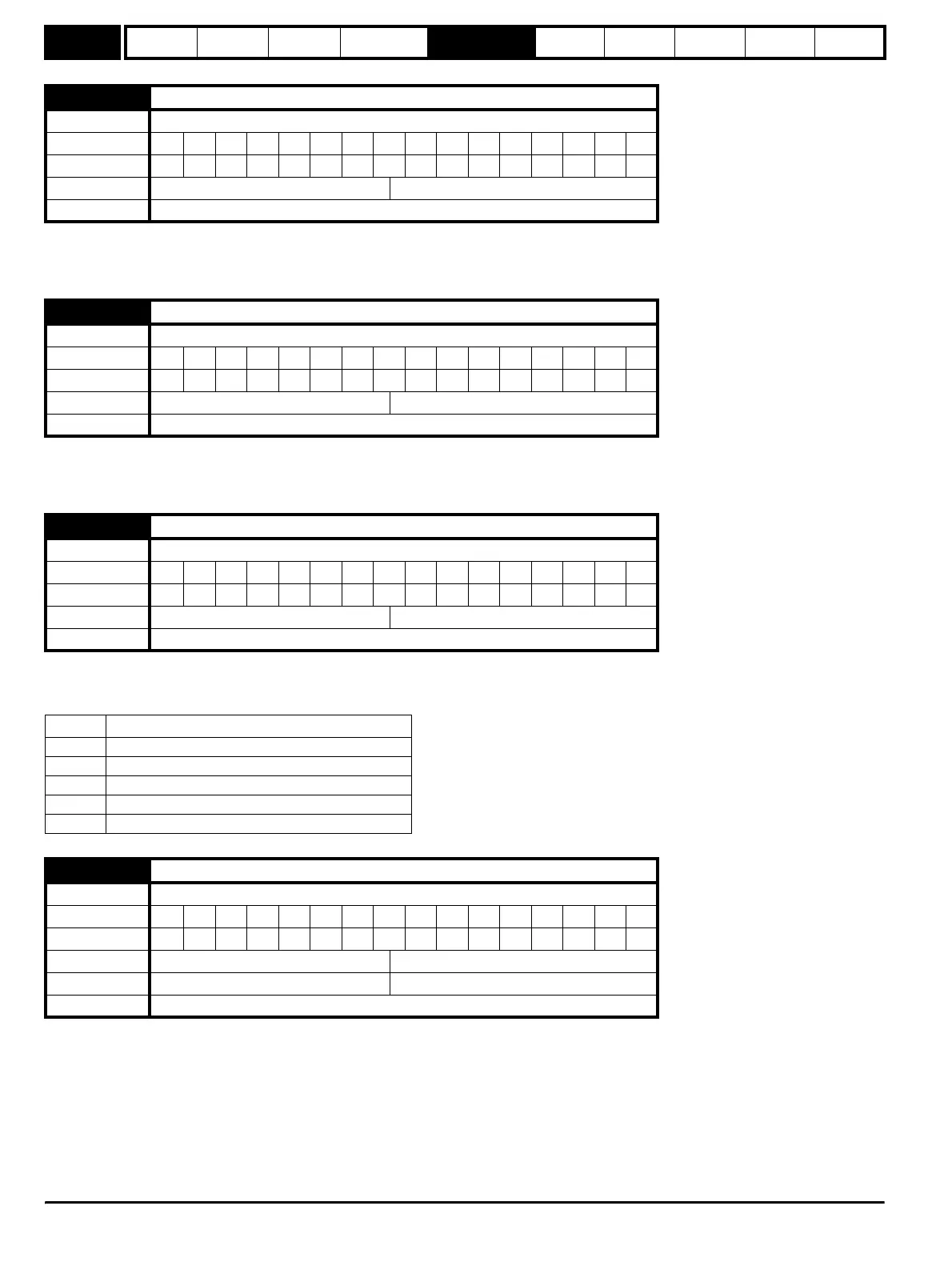
3.01
Reactive power
Drive modes Regen
Coding Bit SP FI DE Txt VM DP ND RA NC NV PT US RW BU PS
1 12111
Range Regen ±POWER_MAX kVAR’s
Update rate Background write
3.02
Input inductance
Drive modes Regen
Coding Bit SP FI DE Txt VM DP ND RA NC NV PT US RW BU PS
3111 1
Range Regen 0.000 to 500.000mH
Update rate Background write
3.03
Regen status
Drive modes Regen
Coding Bit SP FI DE Txt VM DP ND RA NC NV PT US RW BU PS
111 1
Range Regen 0 to 15
Update rate 4ms write
Bit Status
0 Tripped during synchronisation
1 Tripped while running
2 Reason for trip was supply frequency <30.0Hz
3 Reason for trip was supply frequency >100.0Hz
4 Reason for trip was PLL could not be synchronised
3.04
Regen restart mode
Drive modes Regen
Coding Bit SP FI DE Txt VM DP ND RA NC NV PT US RW BU PS
1 1111
Range Regen 0 to 2
Default Regen 1
Update rate Background read
http://nicontrols.com