Menus 15 to 17
SM-Resolver
Parameter
structure
Keypad and
display
Parameter
x.00
Parameter
description format
Advanced parameter
descriptions
Macros
Serial comms
protocol
Electronic
nameplate
Performance
Feature look-
up table
252 Unidrive SP Advanced User Guide
www.controltechniques.com Issue Number: 7
This parameter should only be set to 256 (10 bit resolution), 1,024 (12 bit resolution) or 4,096 (14 bit resolution). If the parameter is set to any other
value the drive assumes the following: 32 to 256 = 256; 257 to 1,024 = 1,024; 1,025 to 50,000 = 4,096. If the drive is operating in Closed-loop vector
or Servo modes and the resolver is selected to provide speed feedback for the drive (see Pr 3.23) then variable maximum SPEED_LIMIT_MAX is
defined as shown below.
It should be noted that for a 2 pole resolver that this parameter defines the resolution over one mechanical revolution, but for a resolver with 4, 6 or 8
poles the resolution defines the resolution over an electrical revolution of the motor. For example with a 6 pole resolver (and 6 pole motor) the
resolution is over
1
/
3
of a mechanical revolution.
The excitation level can be controlled for use with 3:1 ratio resolvers (Pr x.13 = 0), or 2:1 ratio resolvers (Pr x.13 = 1 or 2).
Resolvers with the following numbers of poles can be used with the Solutions Module.
0: 2POLE
1: 4POLE
2: 6POLE
3-11: 8POLE
A 2 pole resolver can be selected as drive speed feedback with a motor with any number of poles. A resolver with a number of poles greater than 2
can only be used with a motor with the same number of poles. If the number of resolver poles is set up incorrectly and the resolver is selected as the
drive speed feedback for motor control Solutions Module error 11 is produced.
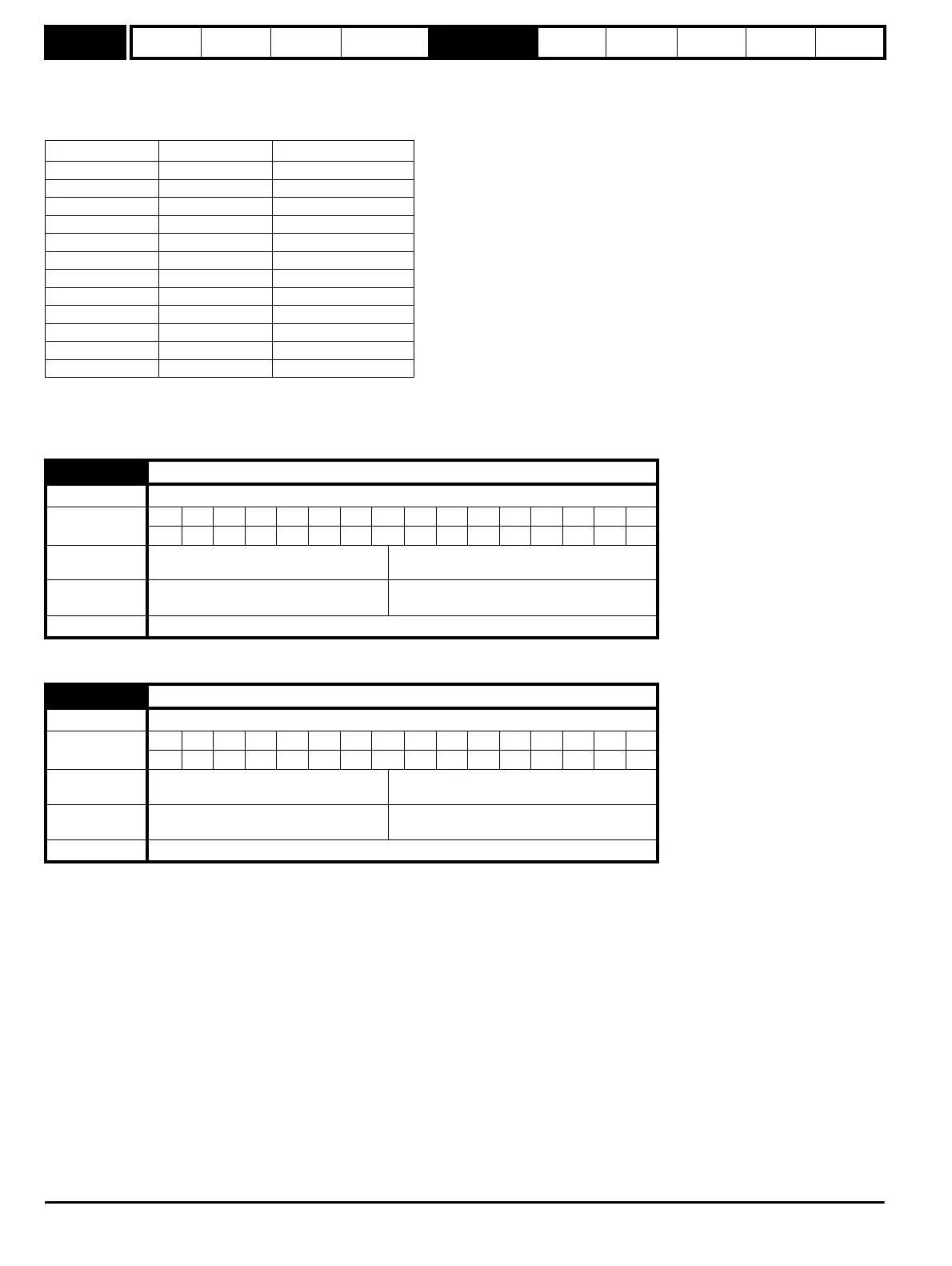
Resolver poles Resolution SPEED_LIMIT_MAX
2 14 3,300.0
2 12 13,200.0
2 10 40,000.0
4 14 1,650.0
4 12 6,600.0
4 10 26,400.0
6 14 1,100.0
6 12 4,400.0
6 10 17,600.0
8 14 825.0
8 12 3,300.0
8 10 13,200.0
x.13 Resolver excitation
Drive modes Open-loop, Closed-loop vector, Servo, Regen
Coding
Bit SP FI DE Txt VM DP ND RA NC NV PT US RW BU PS
111
Range
Open-loop, Closed-loop vector, Servo,
Regen
0 to 2
Default
Open-loop. Closed-loop vector, Servo,
Regen
0
Update rate Background read
x.15 Resolver poles
Drive modes Open-loop, Closed-loop vector, Servo, Regen
Coding
Bit SP FI DE Txt VM DP ND RA NC NV PT US RW BU PS
111
Range
Open-loop, Closed-loop vector, Servo,
Regen
0 to 11
Default
Open-loop. Closed-loop vector, Servo,
Regen
0
Update rate Background read
http://nicontrols.com