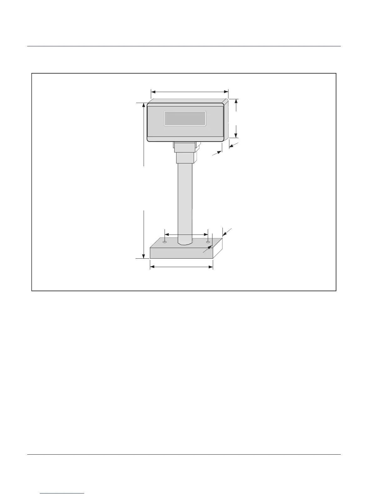
6. Cut the stalk to fit your installation (if required).
7. Route the cable through the base/stalk so that you can plug the
connector into th
e display head.
8. Remove the rubber band from the connector and attach the con-
nector to the display head.
9. Slip the display head onto the stalk/base.
10. Feed the entire remaining length of the Remote Scale Display
inter
face cable through the cable routing hole so that the assem-
bled Remote Scale Display can be positioned over the mounting
scr
ew holes.
11. Install mounting screws or bolts to complete the installation of
the R
emote Scale Display. Take care not to pinch or pierce the

 Loading...