www.dtec.net.au
Chapter 14: Inputs- Using
Pin Allocations
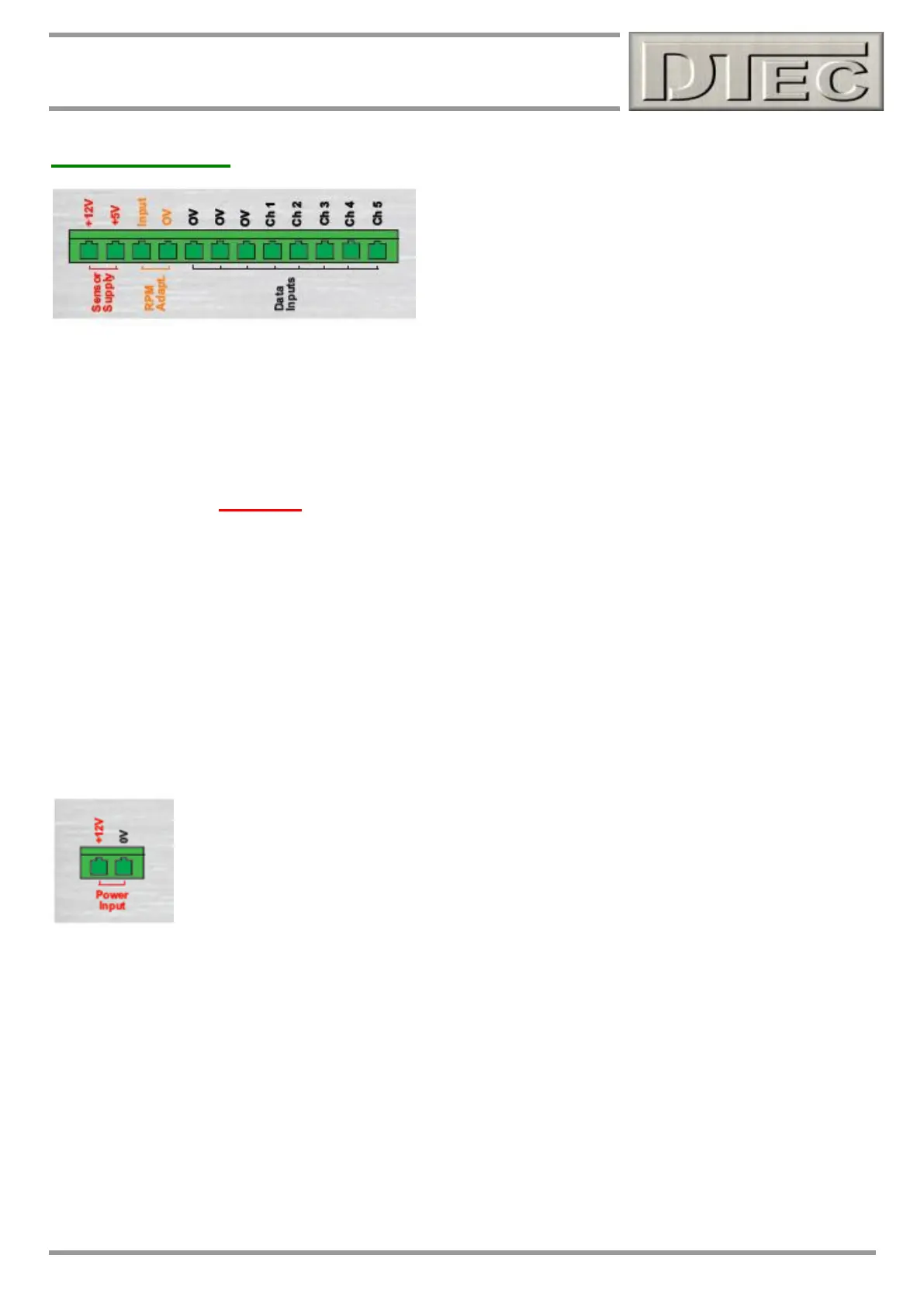
12 PIN Data Acquisition Connector (optional use) – Left to Right
12V output: For supplying sensors with battery voltage if required. Reverse polarity protected. Unregulated.
‘0V’ terminals provide the ground return. Low current, use only for powering sensors.
5V output: For supplying sensors with a stable regulated supply/reference voltage if required.
‘0V’ terminals provide the ground return.
RPM Adapt. input: This is for connecting to an ‘RPM adapter’ or additional RPM sensor. It is a digital input and
must never be directly connected to an ignition system. It needs to be ‘pulled’ to ground and
measures the frequency that this occurs. Please see the appropriate diagram!
RPM Adapt. 0V: Reference ground for RPM adapter input (linked to all ‘0V’ terminals internally).
0V Ground: Reference ground for any inputs being measured (linked to all ‘0V’ terminals internally).
0V Ground: Reference ground for any inputs being measured (linked to all ‘0V’ terminals internally).
0V Ground: Reference ground for any inputs being measured (linked to all ‘0V’ terminals internally).
Channel 1 input: Analogue input for general purpose data acquisition, selectable range (15V Max)
Channel 2 input: Analogue input for general purpose data acquisition, selectable range (15V Max)
Channel 3 input: Analogue input for general purpose data acquisition, selectable range (15V Max)
Channel 4 input: Analogue input for general purpose data acquisition, selectable range (15V Max)
Channel 5 input: Analogue input for general purpose data acquisition, selectable range (15V Max)
Must be connected to any ‘load cell’ input if a brake style dyno is being used.
2 PIN Power Supply for DYNertia3 (must be connected, LED next to it blinks twice to confirm)
12V + input: For powering DYNertia3 (7 to 18 Volts DC is required). DYNertia3 draws typically less than
50mA so very little demand is put on a battery, a cordless drill or bike battery is ideal. A quality
regulated power pack (not just a charger) connected to mains could be used but is definitely
NOT recommended, resistance to interference and stability of the data acquisition signals is
usually better with a battery. This is very dependant on the dyno installation, PC used and
engine types being tested (as to how much interference they produce). Using a battery for
supply also allows extra PC protection as DYNertia3 is fully isolated via optical decoupling
technology. Trial first if using a mains power supply.
0V (12V-) input: For powering DYNertia3 (ground).
NOTE: Both power supply ground and data acquisition grounds (‘0V’ terminals) are all common (internally connected)