www.dtec.net.au
Chapter 2: Hardware Installation
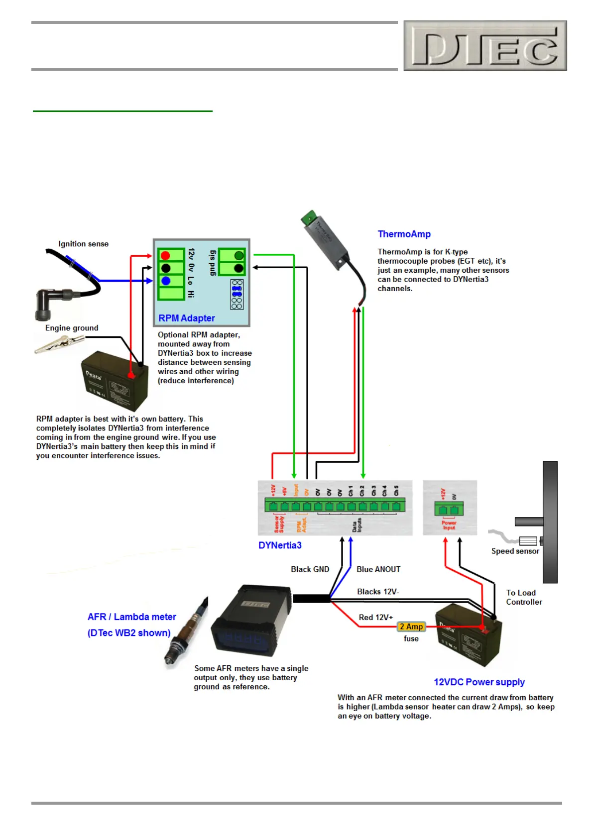
Hardware Wiring (cont.)
Example of typical wiring (additional devices shown)
Please see chapter called ‘Inputs- Using’ of this manual for full wiring details on connection of data acquisition devices.
For brake type dyno’s there will be a load cell and amplifier to be connected to channel 5, this is covered in more detail
in the Brake dyno ‘quick start guide’ and in the chapter ‘Load Controller’ in this manual..
NOTE: In this diagram if the AFR meter was reversed it would damage the DYNertia3 unit. Make sure the meter is not
accidently connected incorrectly to the battery or to the DYNertia3 unit !