www.dtec.net.au
Introduction
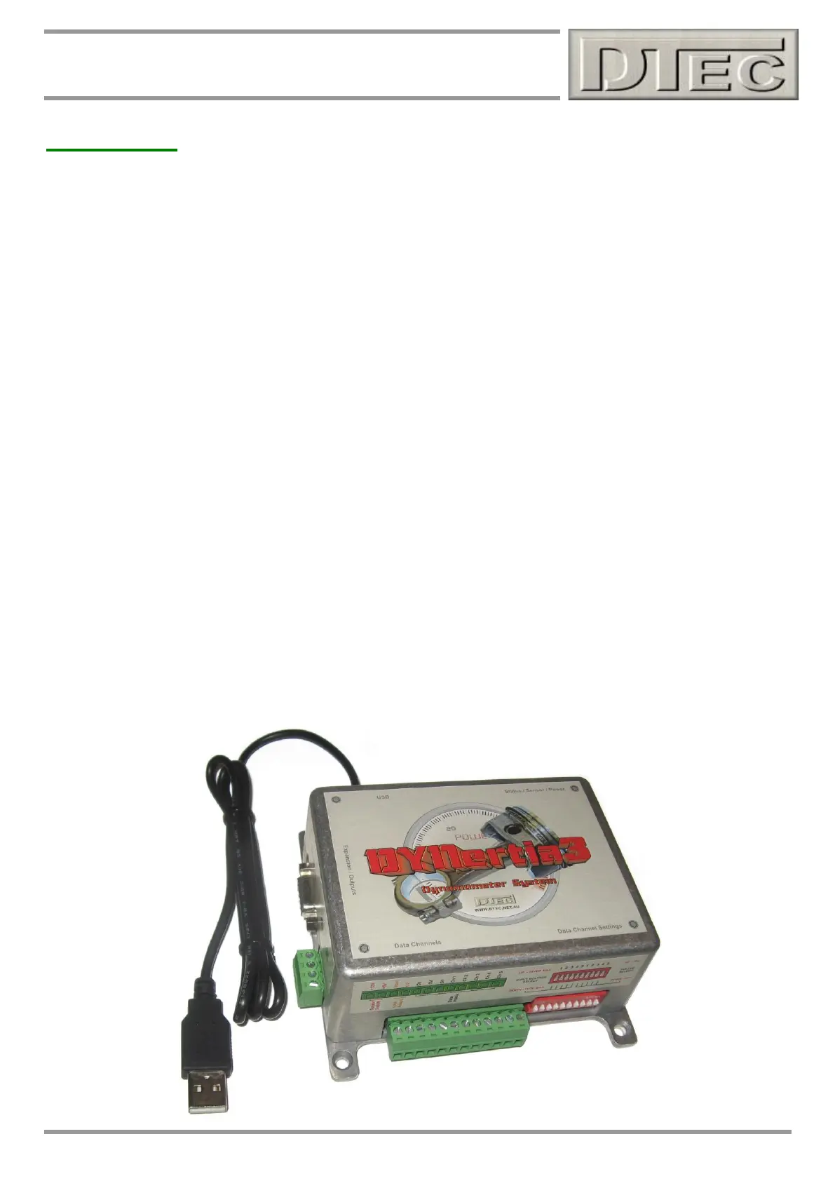
The DYNertia3 Dynamometer package allows for simple and inexpensive "Do It Yourself" construction / upgrade of an
Inertia or Brake Dyno.
Perfect for any one interested in engine / vehicle tuning, testing and modification whether it be car, bike or even model
sized engines.
For those requiring ‘Closed Loop’ Brake control, please refer to our chapter on the optional ‘Load Controller’ systems,
this is an additional unit that interfaces to the DYNertia3 box.
An Inertia type Dyno operates on the principle of calculating the Power required to accelerate a known mass, which is
simply an additional 'flywheel' coupled to the engine or vehicle. The controller senses the velocity of the rotating mass
and outputs this and other data to the DYNertia3 software. No expensive Load Cell is required and repeatability is
excellent.
Brake type Dyno’s use an absorber system (Hydraulic, Friction, Eddy Current etc) to load the engine and the resultant
Torque is measured by a ‘Load Cell’. In ‘Brake’ mode DYNertia3 uses this Torque input and RPM to calculate Power.
The DYNertia3 software package handles all of the functions required for Dyno control: configuration, saving Runs,
correcting for atmospheric conditions, filtering, displaying data, printing, overlaying and analyzing multiple Runs.
A rotation sensor is included with the DYNertia3 Controller; you simply attach a magnet (supplied) to the Inertial Mass /
Brake or drive system. Optionally, we can supply a Hall sensor designed to sense a metal ‘target’ rather than a
magnet, allowing a metal protrusion or tooth to be used as the Sensor "target".
The closed loop Load Controller systems use an alternative sensor system (sensor is still provided by us) as it is
triggered by a target wheel with multiple teeth.
For Engine or Chassis Inertia Dyno's we also provide a comprehensive guide to assist in the design and construction of
the Inertia Assembly. All you need in addition to this is the DYNerta3 package and a PC with a USB port.
Five analogue data channels and one digital input (secondary RPM input) are available for displayed and recording -
these are completely flexible and can be used for sensors such as Air Fuel ratio, Exhaust Temperature, Pressure, Load
Cell, secondary RPM etc. Two ‘Math’s’ channels can be created from any of the existing data (create your own
formulas), just think of the tuning possibilities!