www.dtec.net.au
Chapter 19: ‘Utilities’ Menu
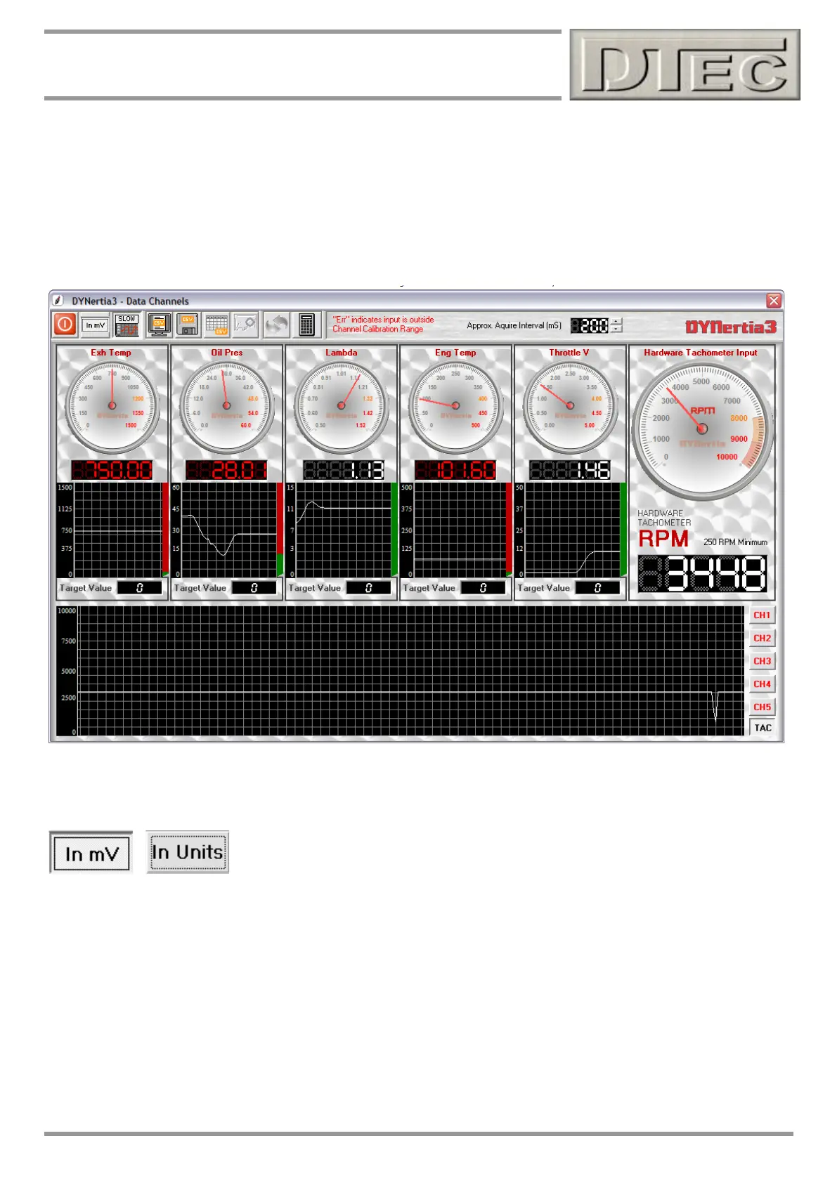
Data Diagnostics
Opens the ‘Data Channels’ analyser Window to test that the channels are configured correctly and operating as
expected. It can also be used for tunning and logging the data.
Note: See chapter “Inputs- Using” for full details on ‘Data Channels’ window.
Note: ‘Hardware Tachometer Input’ will only display if it is enabled in the menu option ‘Setup/Hardware’ and selected as
the RPM source in menu option ‘Setup/ RPM Speed Source’
You can check the naming of channels and that they function. Pressing the “In mV” button allows us to read the voltage
coming into DYnertia3 directly (‘raw’ with no calibrations applied). This is what is used to gather the data for calibration
i.e. you will take this reading and note it against a particular pressure, temperature, position, voltage etc. when
performing a calibration.
Note: DYnertia3 internally reads mV from 0-5000, If you select a switch setting of 0-15V range you are dividing the input
by 3 before it is measured. The ‘raw’ values will be still in the 0-5000 range eg. 9V input would be 3000mV raw.