www.dtec.net.au
Chapter 14: Inputs- Using
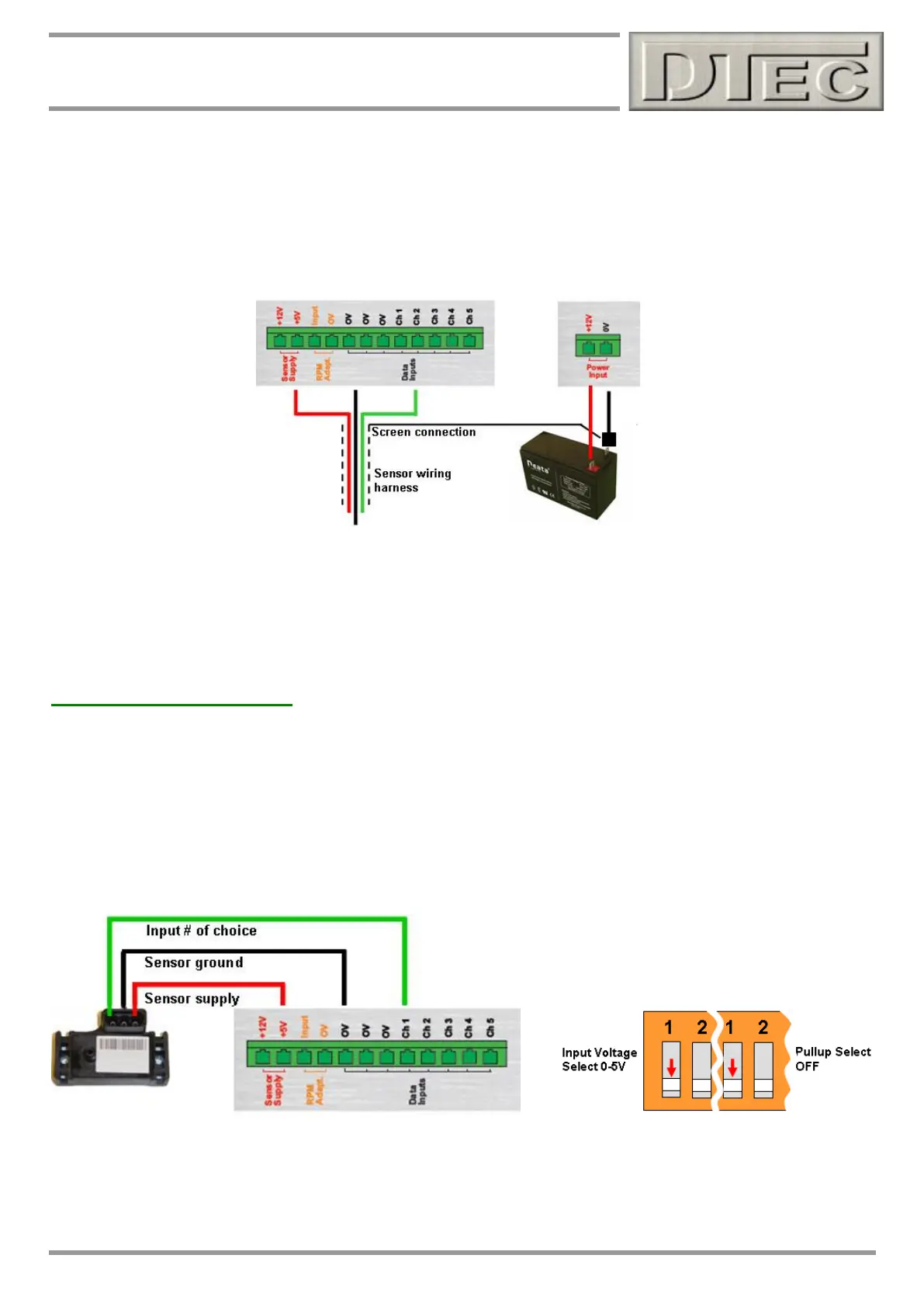
Wiring inputs for best results (cont.)
Quality ‘Shielded’ wiring can be used to help prevent interference from effecting sensor readings. If there are
issues getting good data or for critical measurements this should be considered. Only one end of the shield (or
screen as it is also called) is connected, this should ideally be directly earthed at the negative terminal of the
battery.
View the data input readings in the menu option “Utilities/Data Diagnostics” after wiring to check the readings
before continuing with testing.
Connecting Sensors
General sensor connection (0-5V input shown)
The Inputs can measure any voltage within range (15VDC Max). This voltage may be from a sensor such as pressure,
temperature, position etc or even just a straight voltage such as monitoring battery voltage. You will need to check the
settings in the ‘Setup’ menu under ‘Sensor Configuration’ to let DYNertia3 know the voltage range, display units and
calibration details if required. This is covered at the end of this chapter.
Note: If using a 12V sensor then connect to the “+12V” terminal for supply and set the input voltage switch to 0-15V.