www.dtec.net.au
Chapter 16: Load Controllers
Hardware Mounting & Basic Wiring
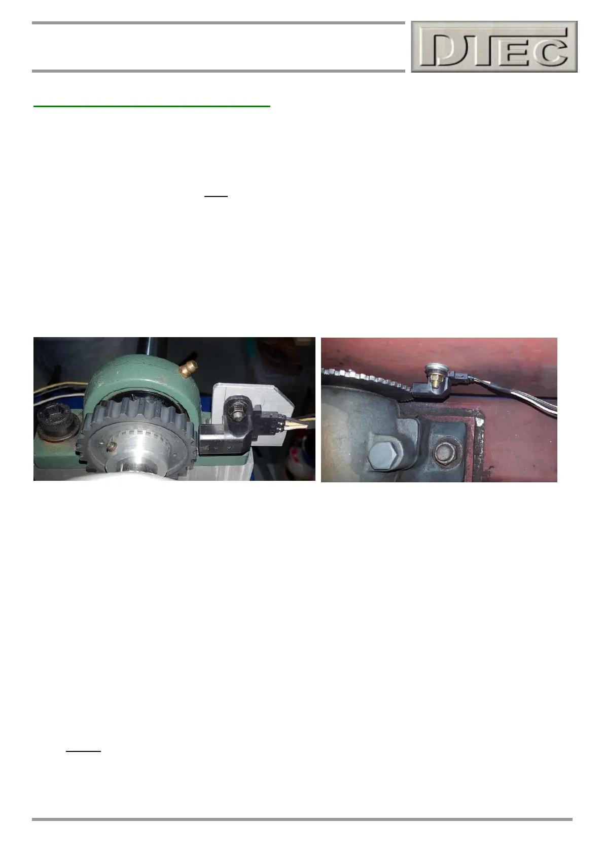
Mounting the speed sensor
Mount the sensor system to detect the rotation of the dyno brake shaft by mounting the included sensor against your
‘target’ wheel. It must be made of an iron based metal (i.e. a magnet must be able to stick to it), do not use brass,
aluminium, stainless steel etc.
Note: The target wheel must have an even number of teeth. The number of teeth is entered into the software so there is
some flexibility in design. Too many teeth and upper RPM is limited, too few and control precision is reduced.
We suggest using a target with between 40 and 100 teeth (60 are common), contact us if any doubts!
Note: We suggest 1.0mm to 1.8mm clearance if you can set this without any chance of collision during operation.
After the gap is set you must slowly turn dyno and check clearance for a full rotation to allow for any ‘runout’ in your
target wheel, quality sensors are expensive!
Observe speed reading when testing (note that software will not display at very low RPM, you will need a test vehicle to
turn fast enough), adjust clearance if required.
DO NOT MOUNT SENSOR AT 90° TO TARGET WHEEL, MOUNT AS SHOWN ABOVE ONLY!
KEY POINTS- Small air gap (with no chance of collision), iron target wheel and even number of teeth!
Mounting electrical components
1) Mount the sensor at the furthest distance from the engine and brake as possible.
2) Keep the sensor leads (speed, load cell, accessories etc.) as far as possible away from the engine, brake power
supply and mains wiring (and any electric motors such as cooling fans).
It’s best to wire sensors with a shielded cable and route sensor cables inside protective metal tubing or keep
separated from any high current wiring by mounting behind the earthed metal of the dyno frame or shields.
Secure at the control units to prevent movement of the cables.
3) Keep the controller and PC at a distance. Coil any spare cable up neatly at the PC.
DYNertia3 software can even be operated by remote control if required (using a cheap PC ‘page turner’ or
wireless keyboard are some options), tests can be started and stopped and new files even created (names
incremented).
4) Always use resistive Spark plugs and suppressed Spark plug leads to prevent interference (at least during
testing).
KEY POINTS- Keep sensor wires away from high current wires/devices, keep all electronics and sensor wiring away
from the engine and beware of un-suppressed leads and non-resistor plugs!