www.dtec.net.au
Chapter 16: Load Controllers
Close to being OK (still oscillating slightly)
Load control system commissioning (cont.)
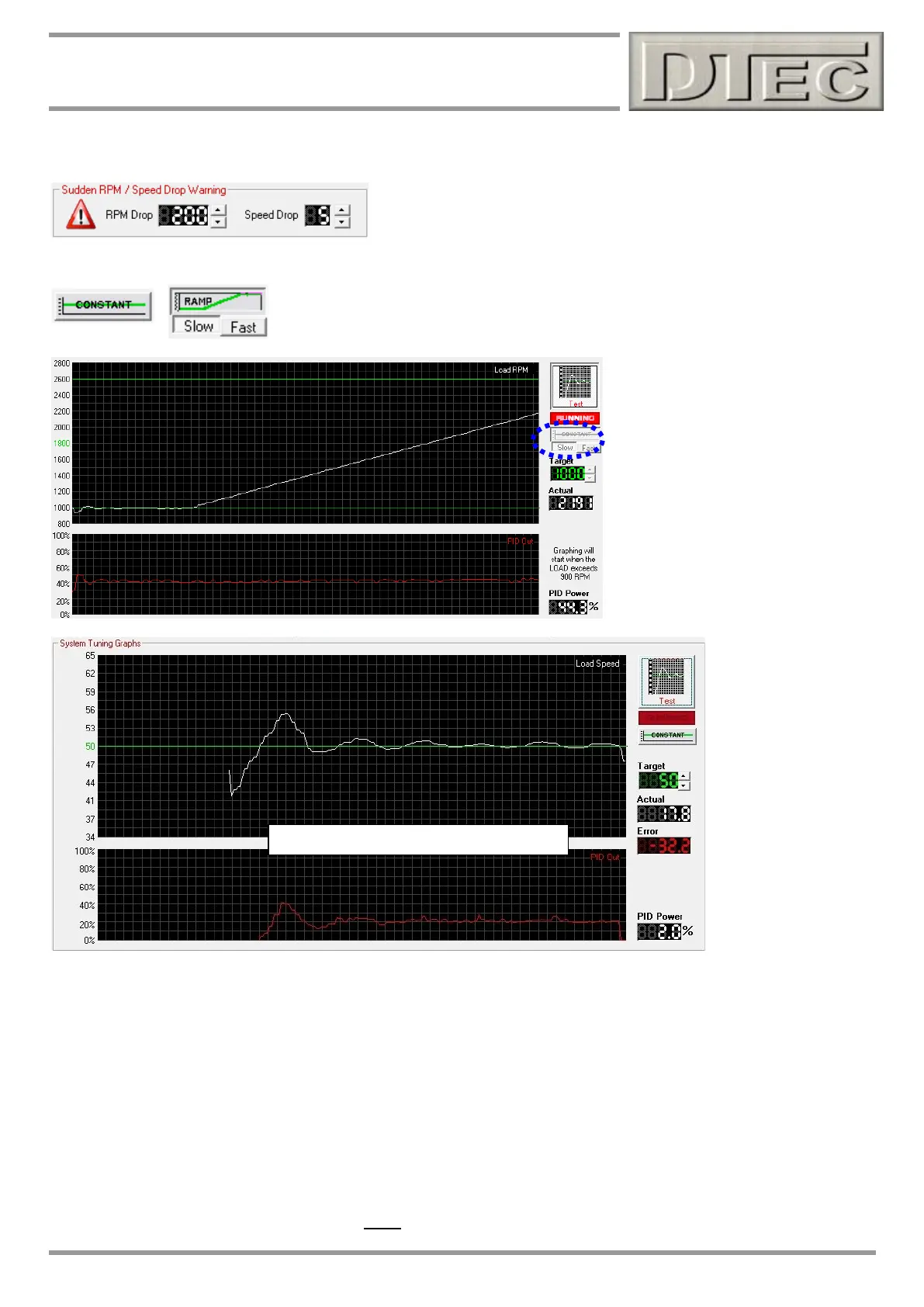
Sudden RPM/Speed Drop Warning: This determines the acceptable
drop in RPM or speed that is allowed when a test is started i.e. it would
not be good to have an engine at high RPM and then suddenly demand
a very low RPM as mechanical damage (or strain on vehicle restraints)
could result.
PID Test Settings: You can set the test format for PID tunning. Usually the ‘Constant’
mode is used for setup and then a ‘Ramp’ is used for confirmation that the PID power
displayed is not fluctuating wildly under an actual ramp test simulation
PID power control smoothness test
after tunning by doing a ‘ramp’ shown
Left (good result)
The method the Load controller uses to maintain the set RPM is called a PID algorithm; this comes from the three terms
it uses to operate (Proportional, Integral and Derivative). A PID algorithm measures the difference between the desired
RPM and the actual RPM, based on this ‘error’ the brake current is controlled to correct it.
Ideal control of the brake would allow the engine RPM to very quickly achieve the target RPM and then maintain it
without large fluctuations. In reality it is OK to have some ‘overshoot’ or to have a small time to settle, these are both
preferred over oscillations (‘hunting’ up and down)! Compromises such as a little overshoot in turn for smoother
operation are often made.
The screen above shows the speed is holding but has a slight oscillation (surge) that should be tuned out, the ‘PID
power’ is very constant as is required for good data during testing (less torque fluctuations from brake), it’s close!
Note: Every dyno design has different behaviour due to inertia, brake power, engine power, gearing etc. so it is not
possible to have one setting for all dyno. You WILL need to tune to get acceptable behaviour when commissioning.