www.dtec.net.au
Chapter 6: Overview- 2 Main Windows
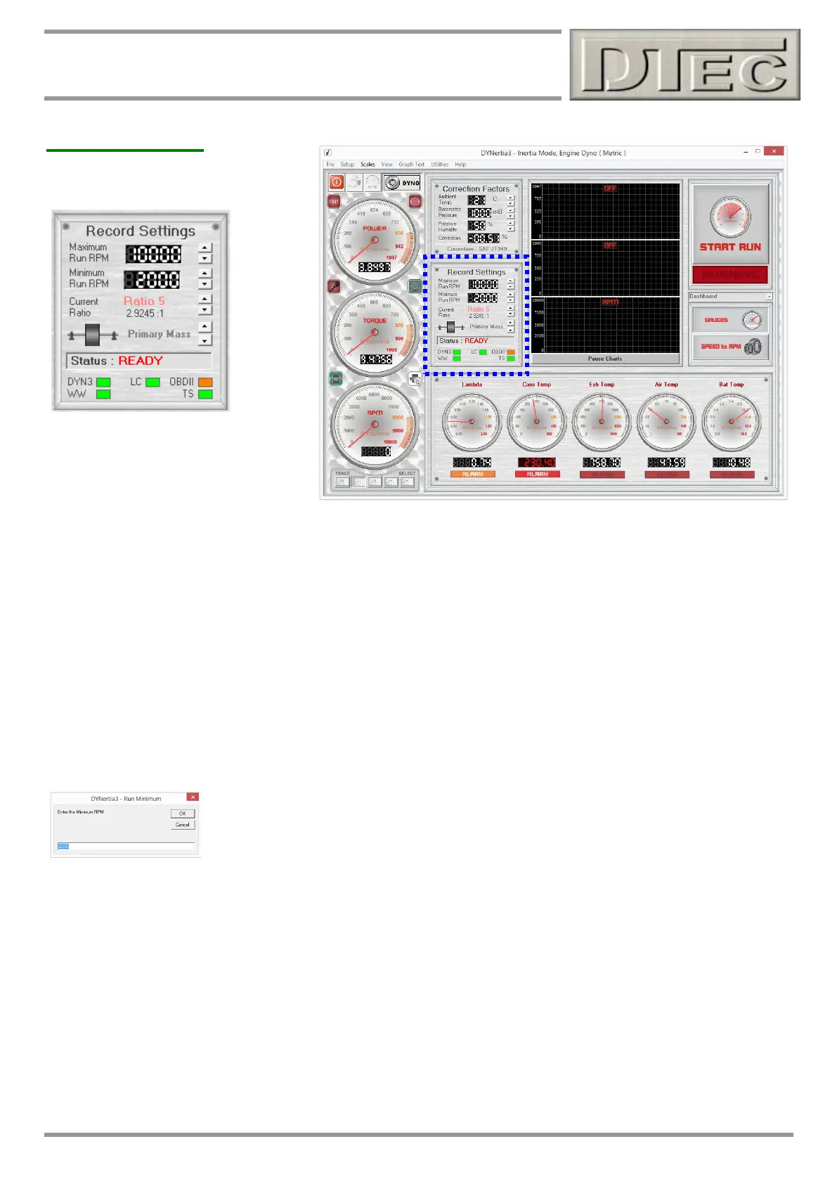
DYNO Window
Record Settings
Minimum Run RPM: Is what you want to start the test at- This sets the point that will be used to start graphing data
when testing. It is usually set just above the slowest speed that you can hold steady on the dyno before you accelerate
for a ‘run’. If set too high your graph will simply be missing data below this speed and if set too low then unsightly
readings may be visible at the start of your graph due to the engine ‘surging’ against the dyno flywheel load as you
prepare to accelerate (inertia dyno). If you have DYNertia3 set to end a test when negative power is detected then a low
setting may also cause a test to end early, this could occur if you decelerate accidentally at low RPM whilst getting ready
to accelerate for a test.
Maximum Run RPM: Is what you want to end the test at- This sets the point that will determine at what point the
graphing screen ‘trims’ off the trace, it does not determine when the actual dyno ‘run’ is over (i.e. it will ignore the data
after the set maximum). It is usually set just below your maximum planned RPM. If set too low your graph will simply be
missing some high speed data and if set too high then unsightly spacing may be visible at the end of your graph.
Note: Either RPM or speed is used depending on the operating mode set. To change the dynos mode use the ‘mode’
tool bar button (icon of ‘gauge’, Top Left of active screen); RPM or speed settings are both stored independently.
Tip- Clicking on the text “Maximum” or “Minimum” will allow direct fast direct entry of the
values.
Current Ratio: The selection here is used by DYNertia3 to work out (derive) engine RPM by relating it to dyno RPM
from the speed sensor and this will depend on the gear being used during testing on chassis dynos.
Set the vehicle gear you wish to test in or select “Shaft RPM” if the dyno is directly coupled to the engine (1 flywheel
rotation = 1 engine rotation). There is also a “User” option for selecting a fixed ratio, this is used for dynos were the dyno
shaft is indirectly driven by the engine via gearing. Ratio data is set with the “Speed to RPM” button (middle RH side of
screen above).
Note: Details about setting ratios are covered in the chapter “RPM Input Options”
Incorrect setting of ratios will result in engine Torque being displayed incorrectly as it is calculated from Power using
engine RPM, Power figures will be unaffected as they are based on flywheel mass RPM (inertia dyno) or load cell &
roller RPM (brake dyno).