www.dtec.net.au
Chapter 14: Inputs- Using
Testing sensor configurations
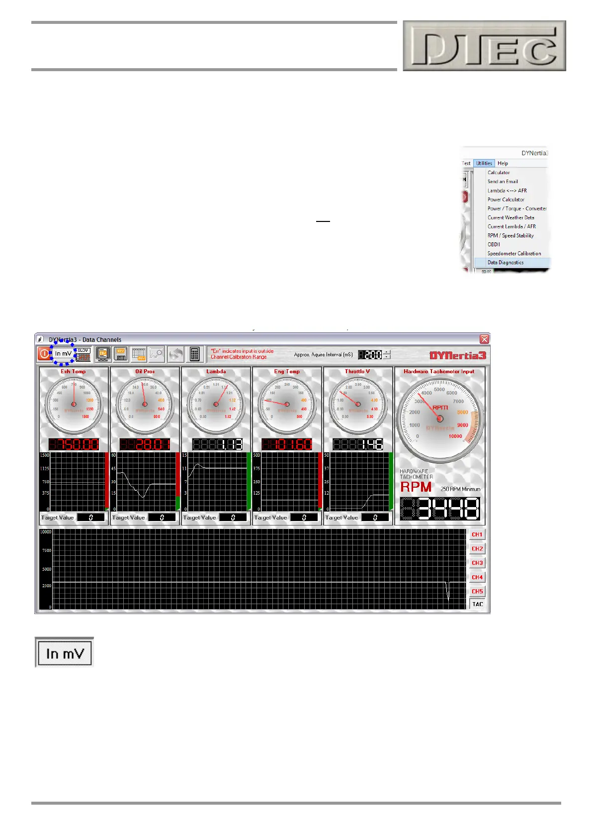
Please use the ‘Data Channels’ analyser Window to test that the channels are configured correctly and operating as
expected before use.
Note: Window is found in the menu “Utilities/Data Diagnostics”, not ‘Sensor Configuration’
Note: See chapter “Live Data Viewing for further details.
Tip- This screen is ideal for calibrating sensors, as in our example for non-linear sensors you can also use the “In mV”
button to display the 'raw' mV readings (0-5000mV), this is prior to any sensor calibration being applied.
You can check the naming of channels and that they function. Pressing the “In mV” button allows us to read the voltage
coming into DYnertia3 directly (‘raw’ with no calibrations applied).
This is what is used to gather the data for calibration i.e. you will take this reading and note it against a particular
pressure, temperature, position, voltage etc when performing a calibration.
Note: DYnertia3 internally reads mV from 0-5000, If you select a switch setting of 0-15V range you are dividing the
input by 3 before it is measured. The ‘raw’ values will be still in the 0-5000 range eg. 9V input would be 3000mV raw.